Modules 6 & 7
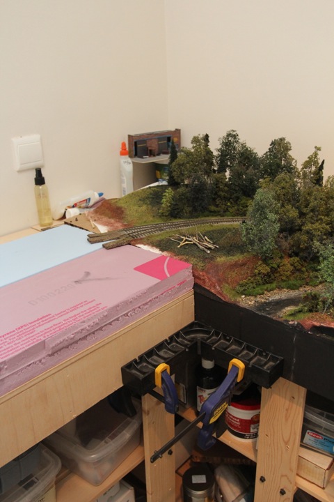
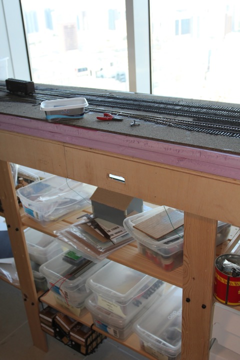
Ok, getting started is always the hardest part. Maybe worse in this case, as the module bases have sat for a long time, working as extra work bench and storage space.

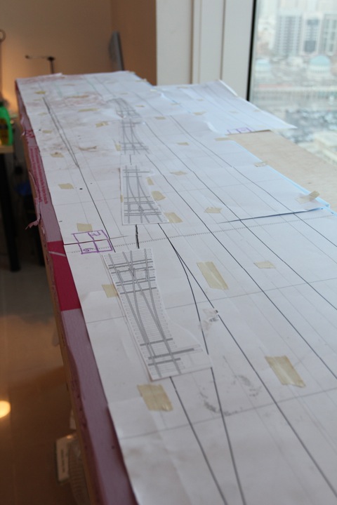
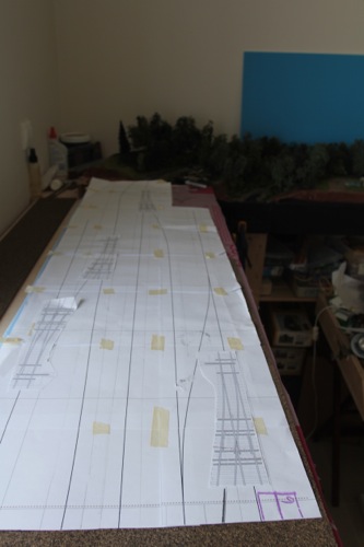
With the junk off, I was able to see the track plan (left on top).
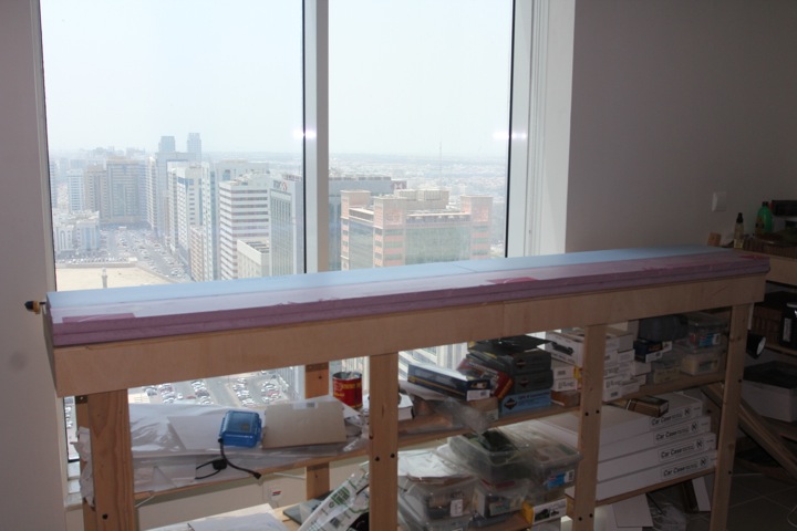
And after making some registration marks, it was time to start. The two module bases were pulled down, and securely bolted and screwed together. As a test, I discovered that I could pick it up and put it back on solo, but it goes much easier with some help. As when I'm doing that it will have foam, cork, and track on it, I'll stick with the help.
Nothing like a clean slate.
Next up was sizing and cutting up the foam underlayment. I need two layers for the right height here, the pink is foam I brought with me, the blue is a single board I was able to get locally (well, a couple of hours away) thanks to Norman's persistence on finding the product.
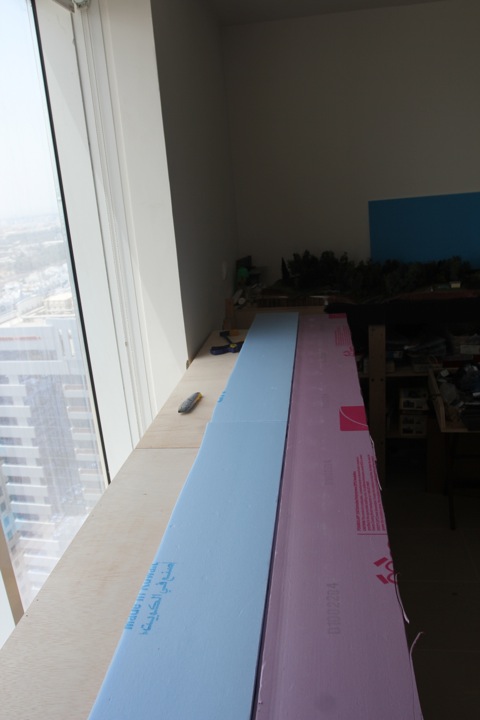
And once that was cut and placed, the bottom layer went down with glue - under my very fancy, very advanced, foam-clamping-system.
First on the list is to check alignment, and to do that, the modules were slid (the wood glides pretty well along the tile) into place.
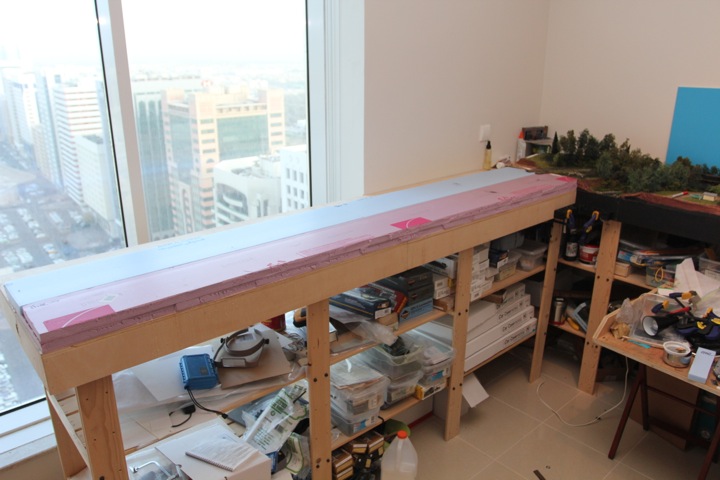
Then, using a 90 degree cabinet angle I got from Rockler years ago (really handy for framing, in case you're interested), clamped it into position.
With that lined up, I used this ribbon rail guage to help mark out where the roadbed should fall.
Pulling out the 1:1 track plan, I aligned it as it's supposed to go.
Uh oh. Missed by a few inches. No stress, as I had decided I wasn't going to worry about that - adjustments can be made now instead on the following modules. I simply don't want to force anything to fit a paper plan.
So, after a few minutes of fiddling...
Now that's looking better. A slight slide to the left and back, and voila - we have an alignment that will work. On the other end?
It works - it's a bit towards the back more than I would like for scenery purposes, but it has one major advantage.
Sliding it to the left (or back of the module) adds another inch easy to the front of the layout (as shown by the pink foam), making it a it a whole lot more fall over friendly. I think this outweighs any adjustments to rear scenery.
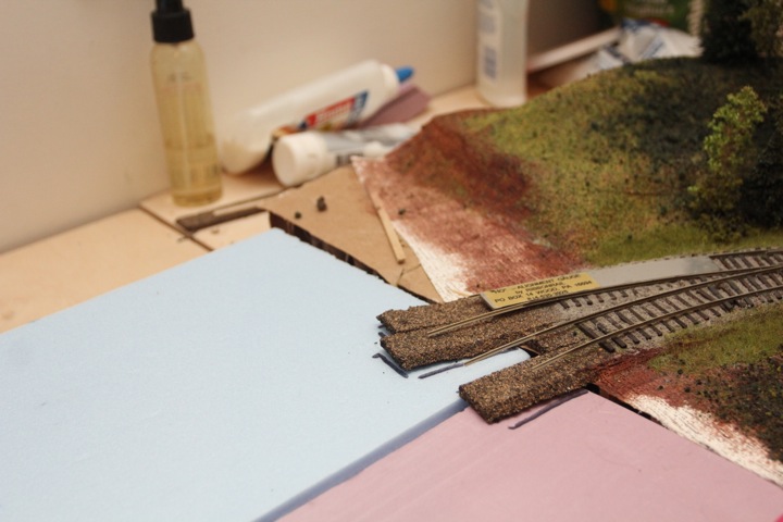
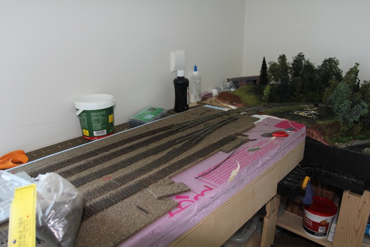
With that resolved (at least in my head), I started plotting out the cork roadbed. Well what do you know.
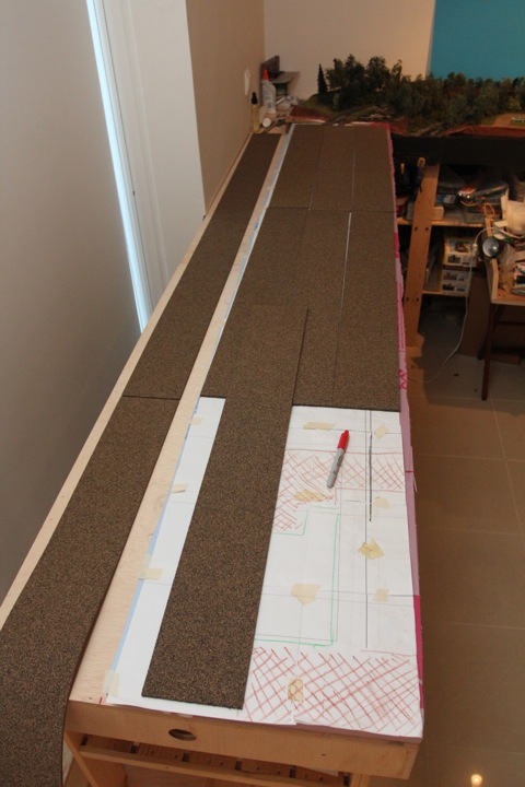
I actually had more than enough! Even after covering this top, I have three more large sheets, not to mention half a box of the split roadbed as well!
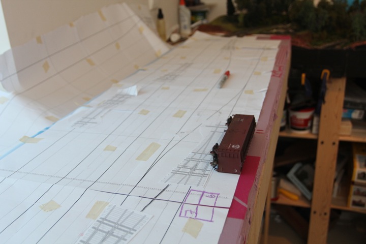
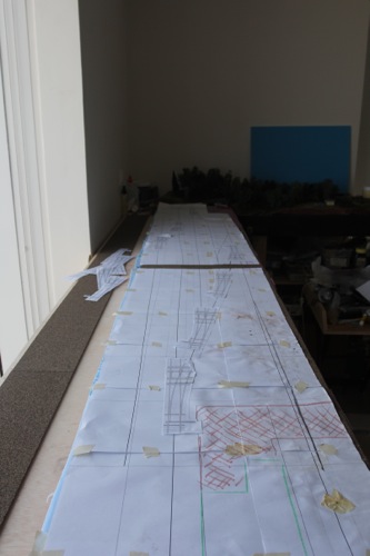
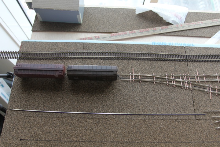
So as I was looking at the track plan on the foam last night, I started to wonder about this track (see B9 below)

I don't really have a purpose for this track...I had marked it as industry, but now I wonder if I should just drop it and add a short track in front of the freight house (box with B3 marked in it, below) or just simplify it.

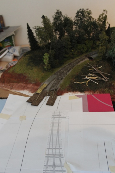
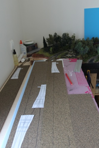
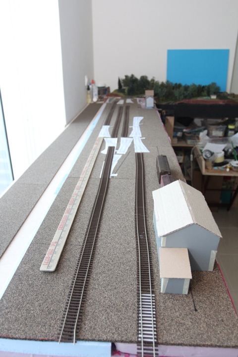
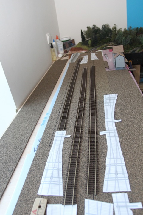
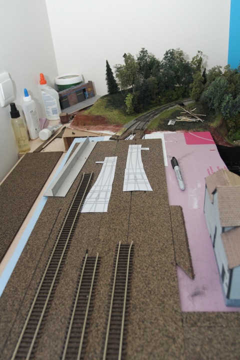
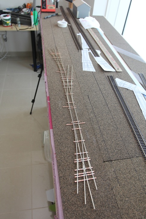
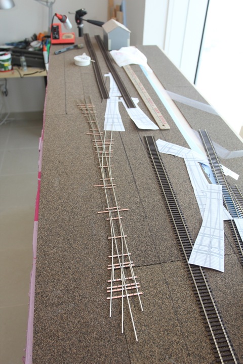
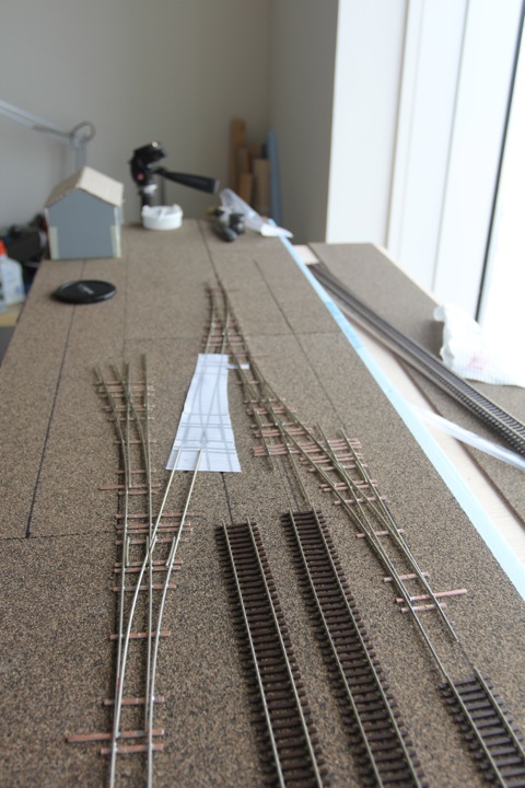
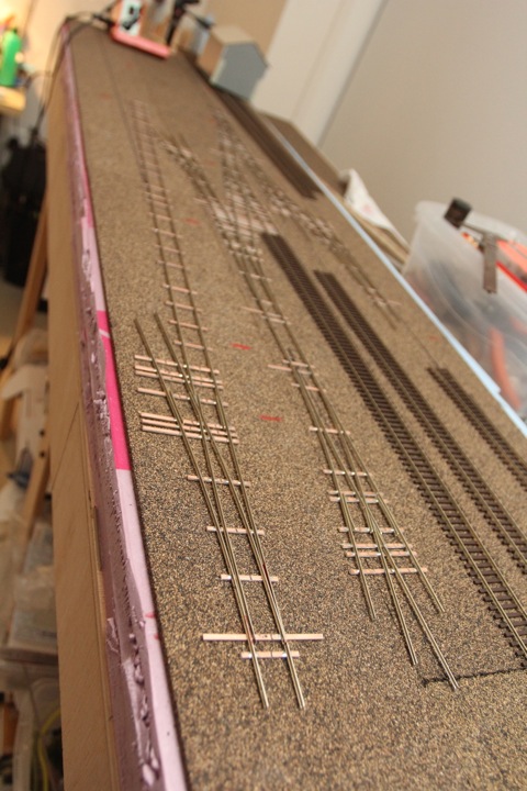
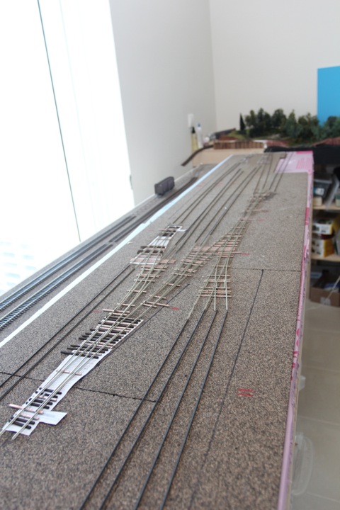
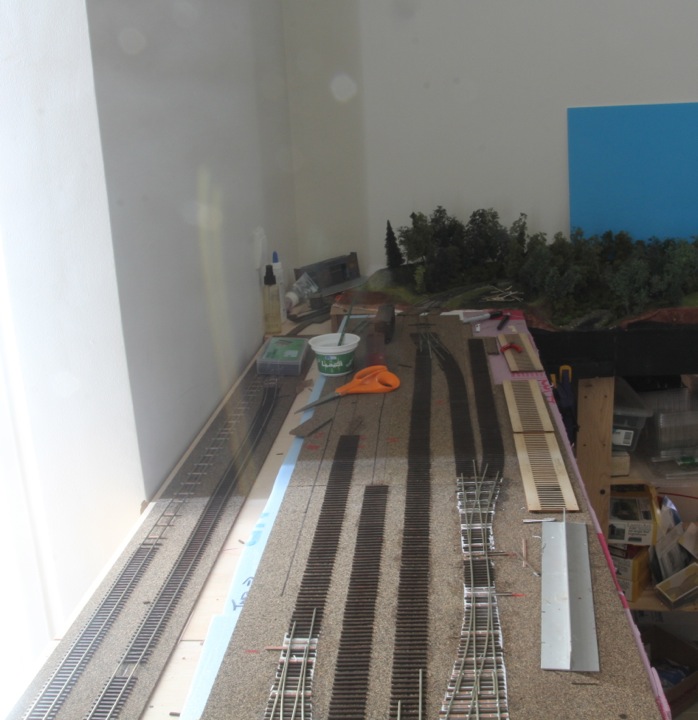
This weekend I got the cork down and in place, and started transferring the plan to the surface.
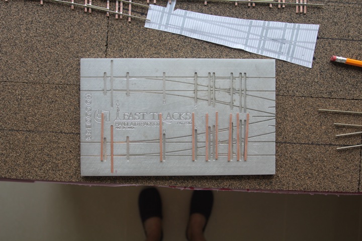
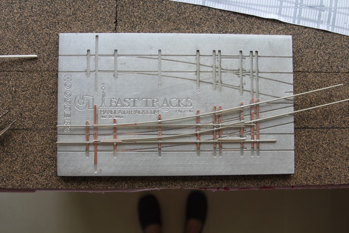
I like to print out the Fast Tracks templates, and slide them around. This is after the cork was glued down, but before the plan was transferred.
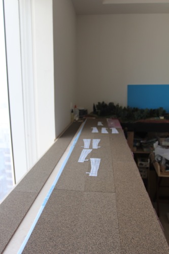
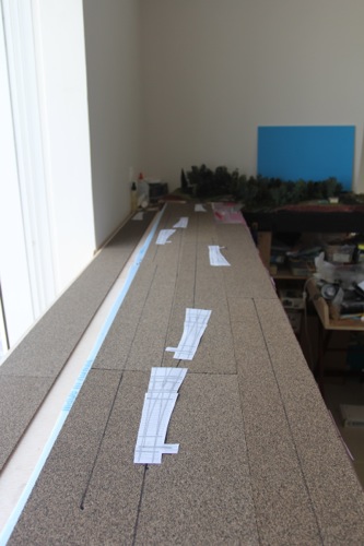
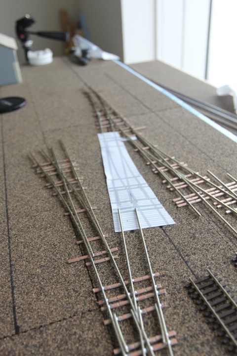
Starting on the connecting end, tried to get things to line up again.
I use a large pencil to punch track centerlines for each turnout, and each track ending. Using these, I try to connect the dots.
I have some time to think on the plan, as I have a few turnouts to get built. I'm going to look at it for a while, and make sure I'm not missing anything.
After a good conversation this morning (well, morning for me) with Jason and Dave, I'm now seriously considering the following plan.

This has the freight house moved to the front, the track shortened, and a short team track added to.
What I don't like about this is the fact that it almost mimics the other side of the layout, but I can live with that.
I think I've finally gotten this to work out.

I've turned the back siding into a passing siding, removing the switchback. Moving the freight house up, and than adding back the other siding provides me a spot for my coal dealer, again without a switchback.
I also slid the yard to the right, shortening the tracks, as I wanted enough room to pull back with at least two cars, both the two middle yard tracks will hold 7 cars (which should be the max for this job), and there is no through track, as this is the end of the branch (it does interchange with a small local road).
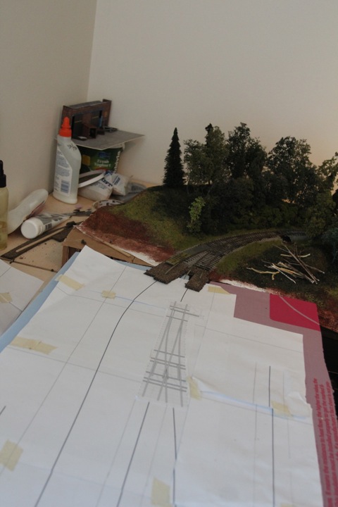
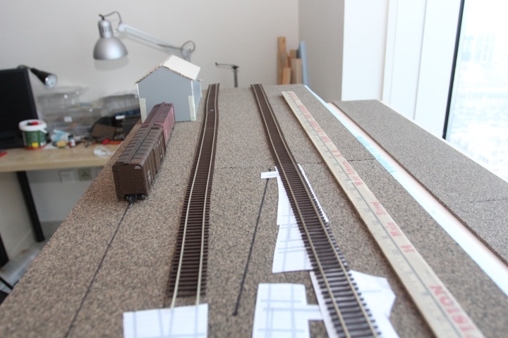
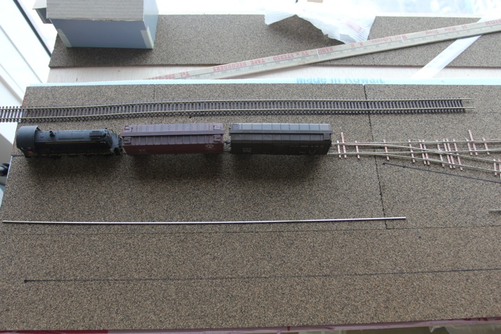
So that's the plan - and to size things up, time to go one to one. lets pretend the yard stick is the track for the stone works.
This team track (or off layout industry) to the front of the layout will hold 3 cars, two easy.

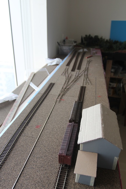
Moving down the layout...
Looking back towards the freight house (team track on the right).
So I'm getting happier - I'm greedy with wanting more track, but I think this scheme will allow for better operations.
Track Work
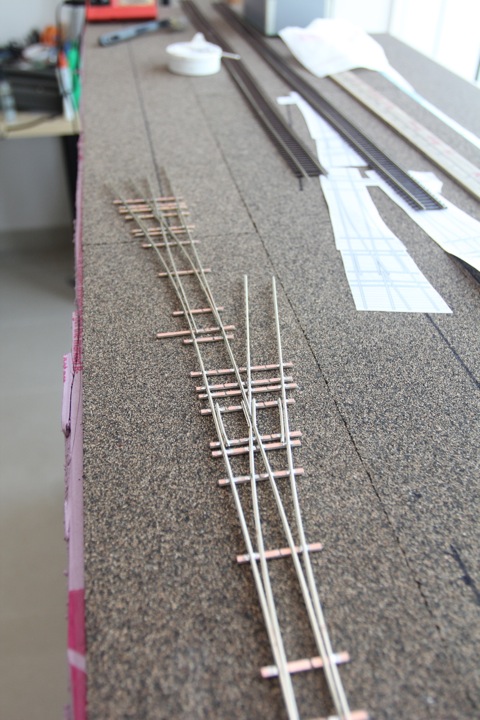
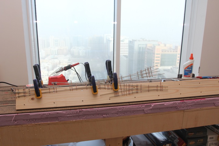
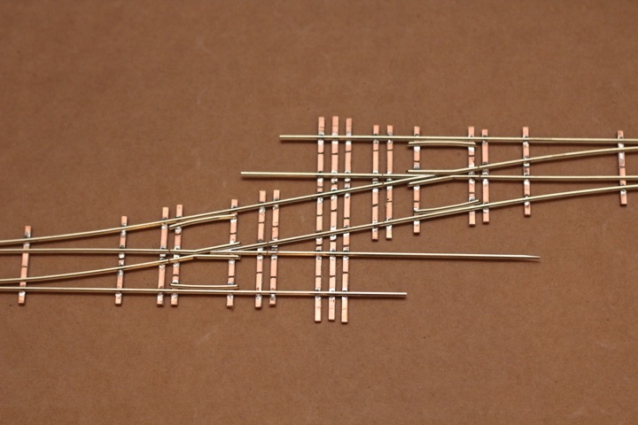
After a busy week of work, I managed to get back in the train room, to create this monster.
I know, not too scary. It's all one piece, all three turnouts share the same bottom rail. There are probably more good reasons to not make it this way than to, but I have fun seeing what I can come up with out of the Fast Tracks jigs, and the lack of rail connectors is kind of nice.
Here's where it goes.
I thought about integrating the other three at the far end as well, but it just gets unwieldy. I think I'll do those three as a set though.
Fast Tracks are fun, no doubt.
Ok, just 7 more turnouts to go....
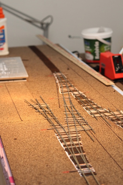
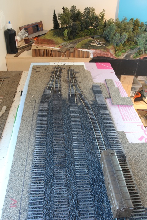
We're socked in this weekend with over 100 degree (f) temps, and a sandstorm - perfect model railroad weather. There are a lot of pictures in this post, I hope you have the patience to go through them, and I hope they work for folks.
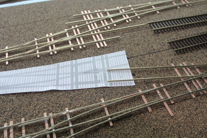
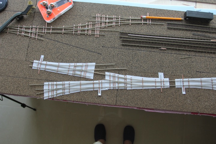
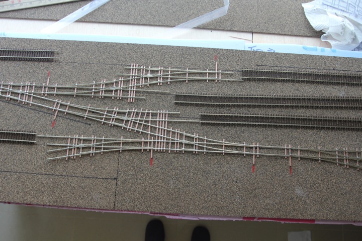
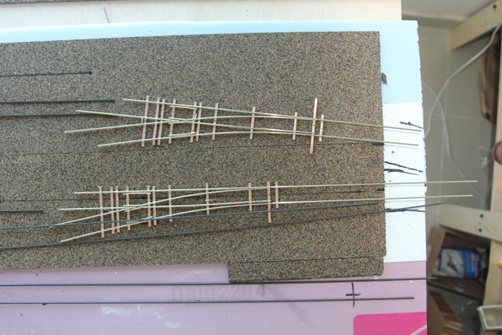
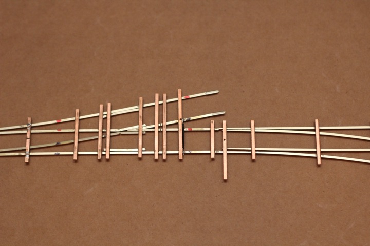
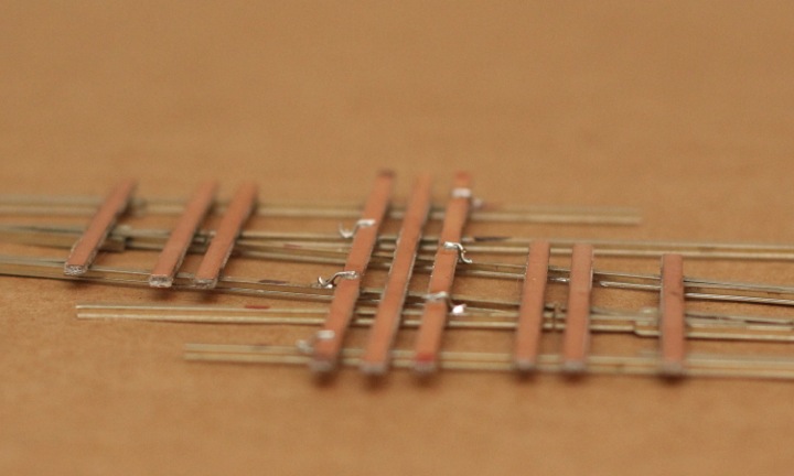
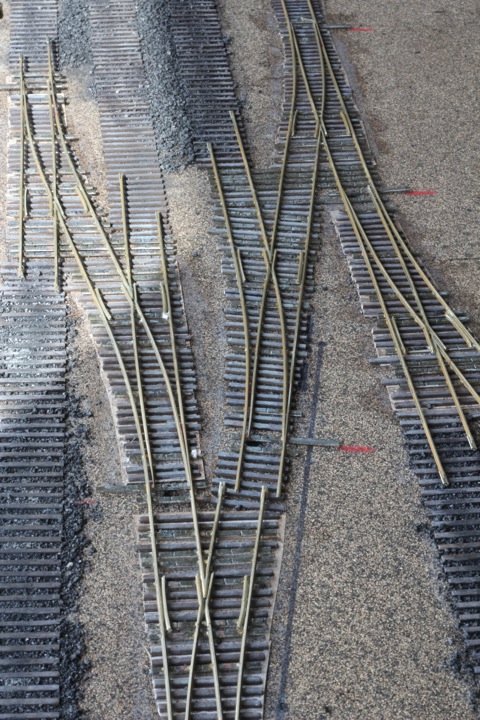
Ok, so...I started by building another "set" of turnouts - this one with the single cross over.
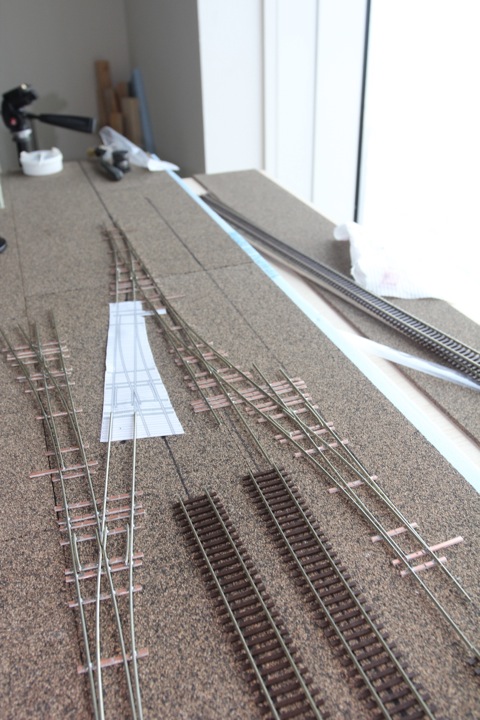
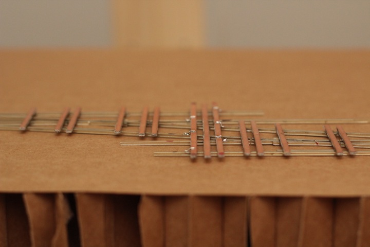
Once complete, I put it roughly in place to eyeball it in comparison to the first "set".
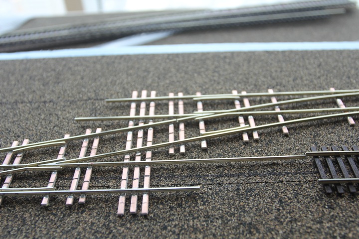
While I almost stopped there for the day, I decided - why not just make one more, and finish off this end of the module(s).
I hadn't intended to hook this single into the set - but than I said why not? I can just use the end of the rail as a gap, and while I won't have a solid rail on the other side, I can live with that.
I had done the exact same thing earlier today with the second "set" - that's how I built the crossover. Here is a kinda close up of that gap, as well as some additional crossover crossties I put in for strength.
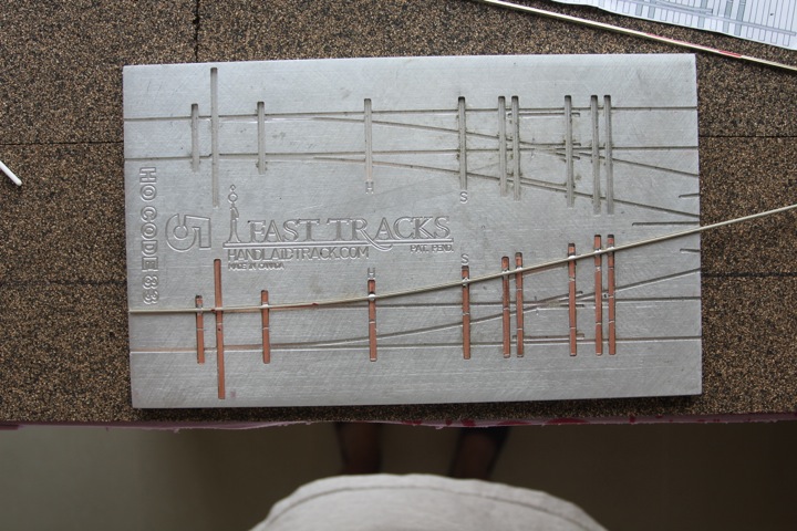
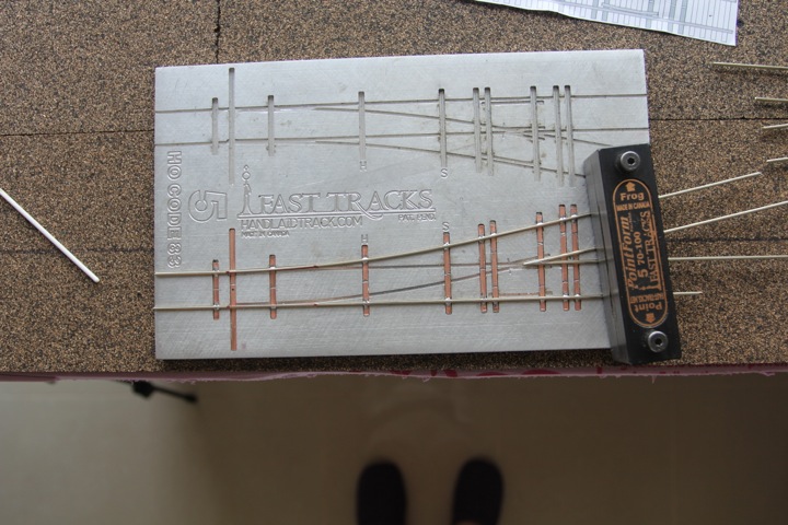
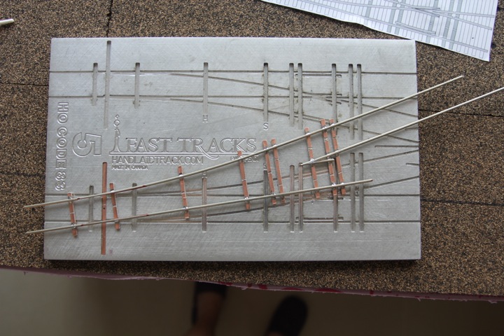
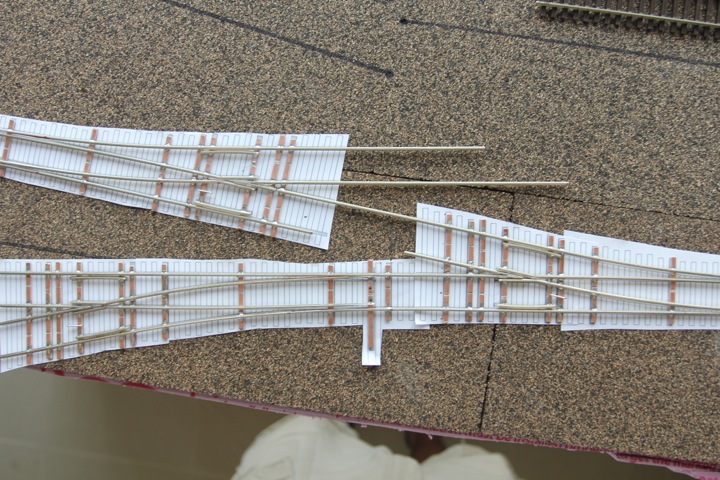
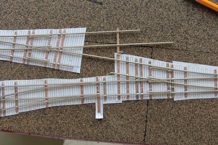
So with that in mind, I thought I'd get started. Than I thought to myself - why not make this a step by step (sort of) for folks who may come across the same situation? Why not indeed. Feel free to skip to the end if this isn't your cup of tea.
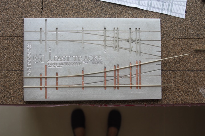
Sizing up the ties.
Cut ties in place and marked for gapping.
Ties gapped (and throw bar hole drilled - its much easier at this stage).
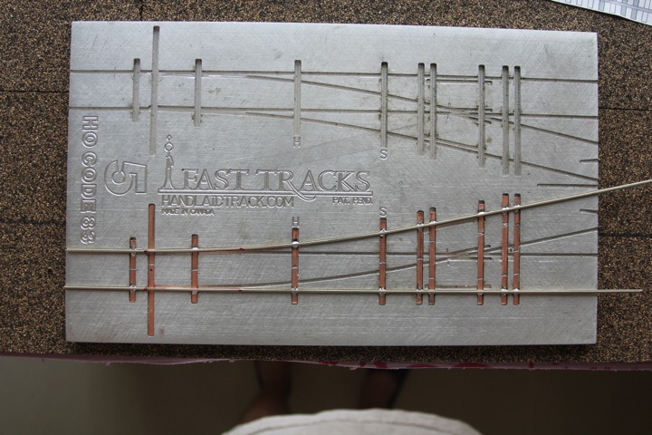
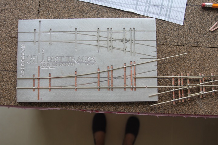
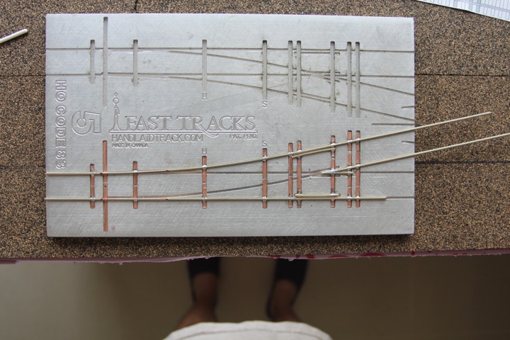
Outside rails are measured, than the rail web near the points is filed away.
The diverging rail soldered in (no nasty comments on my blobby soldering jobs - if you know what's good for you).
Then the stock rail.
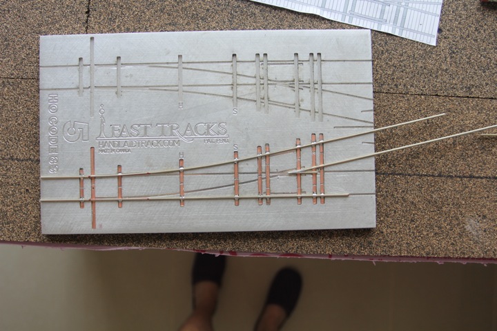
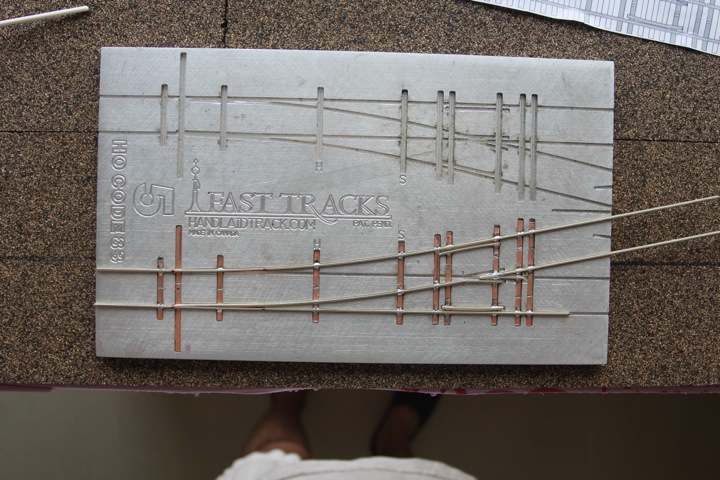
This is just to show that at this point, you can easily remove the skeleton from the jig if you need to safely.
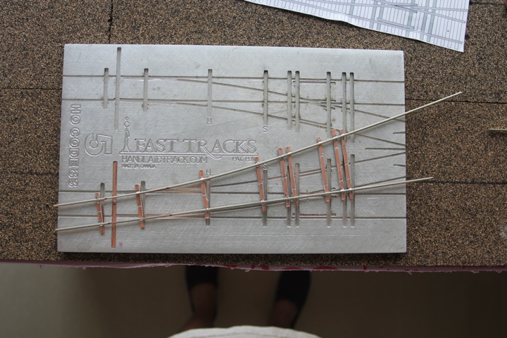
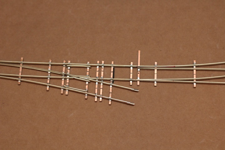
Back in the jig, the frog is lined up. Note that even though I'm going to cut back on side of the frog severely, it's much easier to work with a longer length of rail and cut it back than it is to fiddle with a small section.
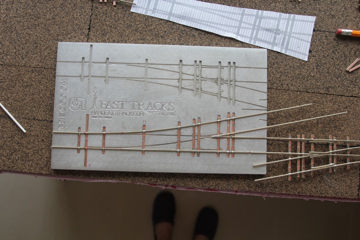
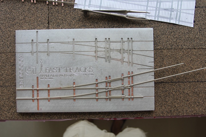
With that looking good, the frog is soldered together (not to the ties yet). Observe clever clamping tool.
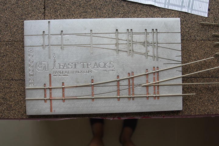
With that soldered, it's removed, and the turnout that's going to join is measured up; the rails are cut to the appropriate length for the frog gap and the outside rail.
I mark the jig in pencil, and sizing up the frog, cut it accordingly.
Then, before soldering, another line up.
Looking good, the frog is soldered in place.
From here, it's a simple matter of continuing the turnout. Guard rails (for me) come next.
Then the points.
Once they are soldered to the throw bar, the turnout's really pretty complete.
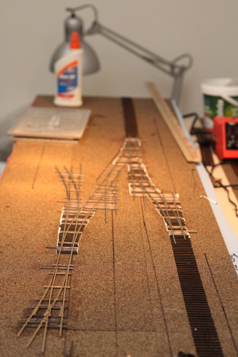
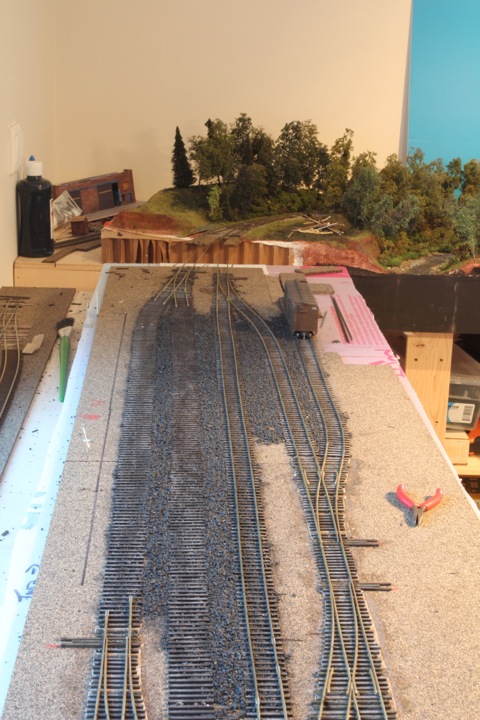
Moving it off the jig, and onto the cork, I size it up against the other turnouts.
What!
Somehow (clearly base stupidity), I mis-measured. Not this bad, really, but too long of a gap to fill easily, so I cut it back to provide the insertion of a longer (and hence in my mind) more stable piece of rail.
Other than that, it looks pretty good, and back in the jig for a second to solder in the other side of the frog gap to the other turnout.
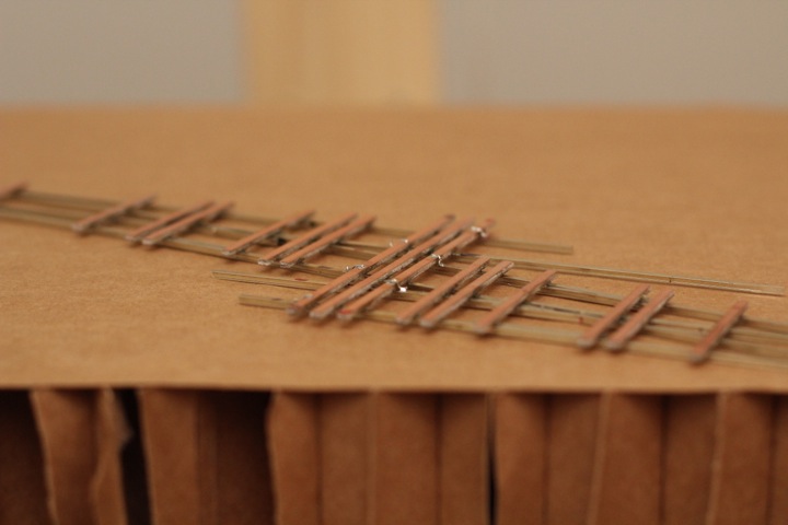
Back on the cork. I must say, cork and foam underlayment makes pinning very easy. In this case, I could pin the whole thing down, and use additional T pins to hold additional ties like this large crossover tie in place while I solder it to the rail(s). The Fast Track templates come in very handy as well - thanks Tim!
So I gapped the missing section of rail, and plugged in a ton of these cross over ties. The result is a very strong set of switches. Off to the sink for a good washing, than back to the layout.
Note that these two sets are not fixed, the top three turnouts are still separate (here connected with rail joiners).
Not a bad weekend's work, if I do say so myself. Just need to gap and solder feeder wires, and they can start going down.
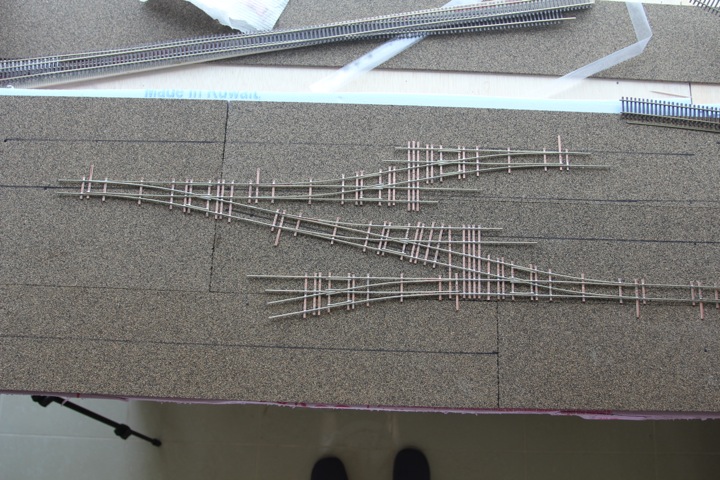
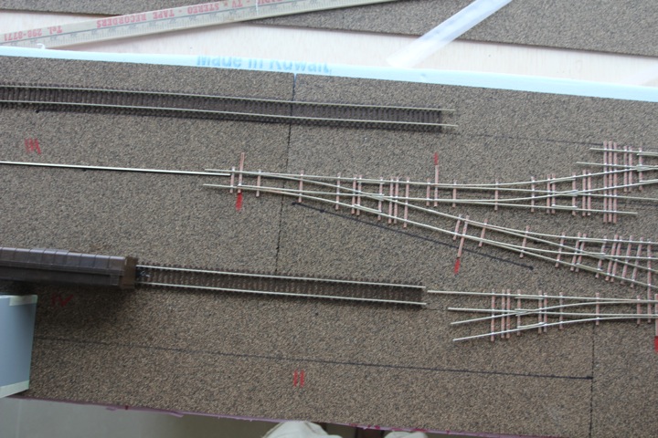
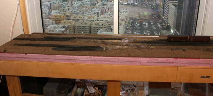
I checked alignment again, and was frustrated to find that I hadn't left enough room here for more than two cars.
This is an issue, as at least for the foreseeable future, that's the end of the line - and I wanted enough room for a loco to pull two cars past the switch (or at least enough room for a steam loco to pull back one). That means sliding everything to the right. The black sharpie line in the next photo is the old center line.
This does mean the other tracks change as well. How? well for starters, the freight house track will now hold 4 instead of 3 cars.
And the other tracks shrink. From the top down, 4, 6, 6, and 3 cars.
I think those shorter (the middle two used to be 8 and 7) tracks are a better compromise from an operations standpoint than the end track being unusable. Most incoming traffic should be no more than 7 or 8 cars max, and if they are longer than 6, well, that will just have to be another bit of fun for the crew as they split it in the yard.
Finally, I took my red pencil and marked the throw bar locations.
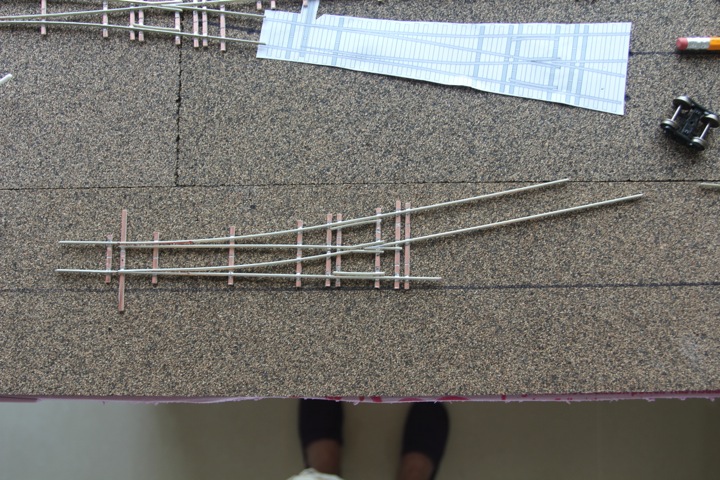
Tonight's adventure was a code 83 left hand number six turnout. With a bit of an extension.
This is for the single turnout on the hidden staging tracks, the extension was to compensate for not enough flex track on hand. I made it easy enough, simply by sliding it along the crossover template and soldering in ties every so often. Doesn't have to be pretty, just functional.
so that just leaves two more number fives to go....I hope I have enough rail!
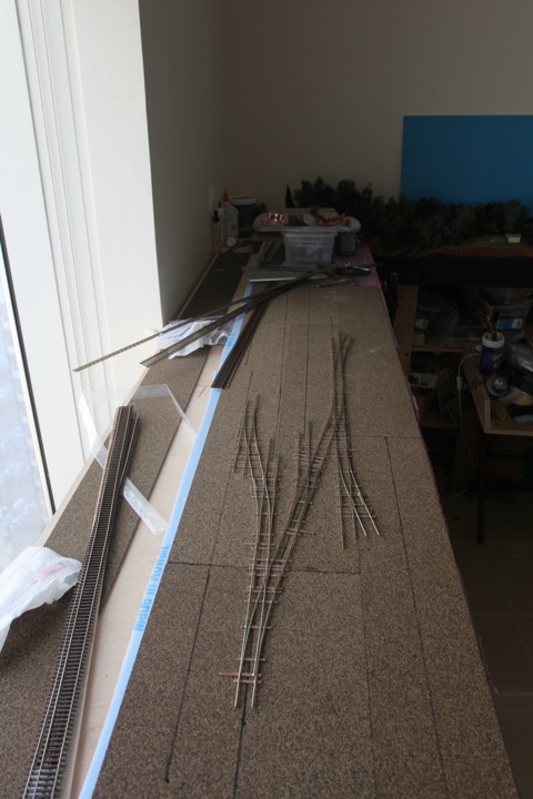
So its the start of my weekend, and now it's end of my turnouts. The last two have been manufactured, and are ready for wiring and gapping.
Makes me kind of sad, actually - making turnouts in the jigs is an activity I enjoy, it's disappointing in a lot of ways to be done with that part of this layout.
The good news is each turnout is basically just a couple of bucks now, between this layout (20 turnouts) and the chainsaw 2 (15), the three jigs I've purchased over the year, the turnouts are now averaging just over $10 (not counting materials). And that doesn't take into account the double crossover.
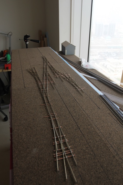
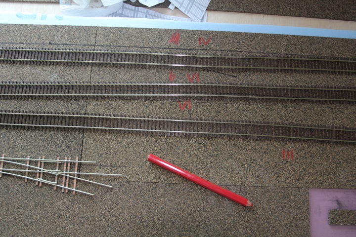
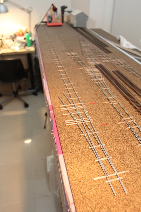
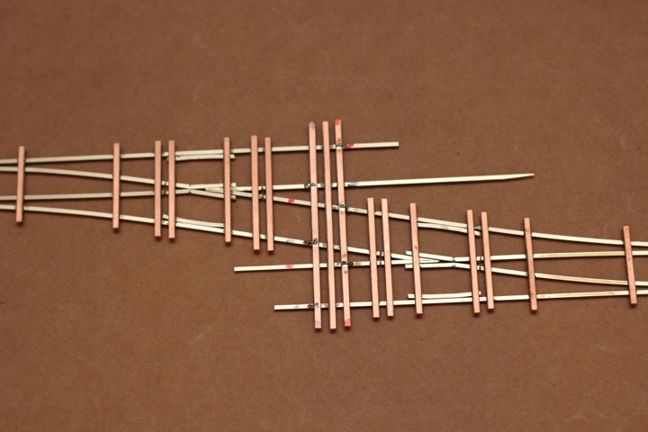
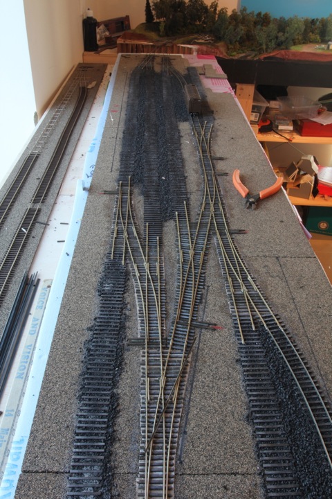
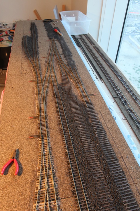
But as I say, the bad news (for me) is that's over for this layout. I got them lined up, and started sizing up other materials, like the rail that goes in between - shown here by the thin black sticks.
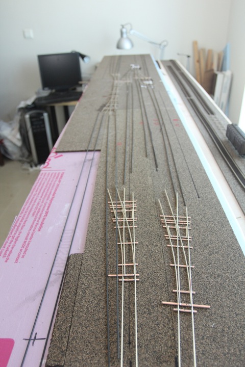
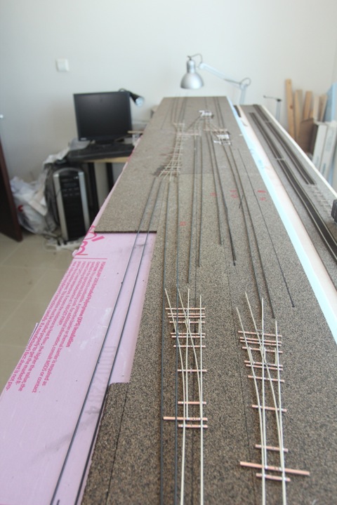
The further good news is I have enough rail - but rain joiners, not so much. Not a big deal, as we're headed back to New England for a few weeks in July, but I do need to make sure I don't run out of anything else before I go. Tomorrow I'm going to gap and electrically check these, including soldering in feeders, and than placing them on the layout so I can begin putting in ties.
Progress = good!
Back to the layout - I have the staging tracks 95% finished, all of the track is soldered together, feeders dropped, etc. The only thing really left to do is add a couple of wooden ties around the points to really solidly anchor the turnout, an connect the track from the other module.
Note the track was glued down using good old fashioned white glue. I have to admit things do go down faster with flex track, but I'm not sure I like it any better.
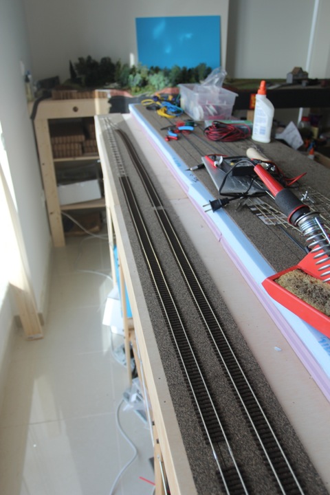
For instance, I dropped in the feeders from above on this section (normally I solder them to the rail before it goes down), and found myself frustrated trying to hold the feed to the rail and soldering gun...and this is something I know most people do all the time. It's all what you get used to.
No ballast on these tracks, they're done, done done - as this is staging, I don't see any need to go that route — unless someone can suggest why I should?
Putting electrical gaps in turnouts is one of my least favorite parts of making track work. I've simply never found a method that I like, that is easy to do and still produces the results I want.
I finally gave up a couple of years ago, and ordered the jeweler's saw that Tim Warris recommends from Fast Tracks.
Even that tool, while ultimately producing a nice narrow cut, has been hell to work with. Trying to put the blade through the turnout, hold it without pressure with one hand while trying to feed the loose end into the clamp, tighten that down, and than adjusting the bow pressure with another one can be a maddening exercise.
Despite broken blades and a bruised ego, I've been somewhat successful as I've gone along. Now, however, I was facing 10 turnouts with only three new blades left in the package. Based on past history, I was going to be woefully short of blades. Adding to, as some might say, the challenge, was my earlier decision to not build these turnouts individually, but instead as sets.
Yesterday, before a scheduled tee time, I laid into the work. An hour later, I was stunned to not only cut the gaps on the last turnout, but realize that I still had two unused blades! I know you're supposed to get better as you do things, but as I hadn't observed this in the past with gap cutting, it was shocking.
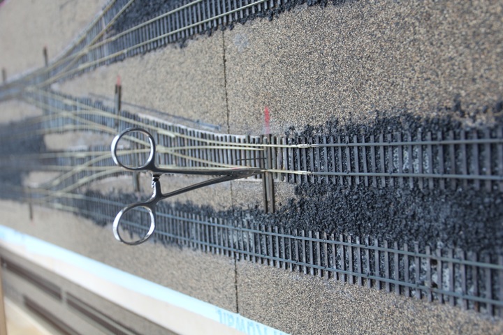
Holding the work securely is a big part of successful cutting. Turnouts are by nature an odd shape and you are cutting in an odd place within it. So here's a picture of my elaborate, carefully constructed "jig".
The clamp shafts actually hold the work at a good angle for cutting; the turnout (and the area) being cut is in between the two on the right. I slide the cutting area just over the edge of the board (a spare riser from the GORM shelving), and have at.
Now, with that odious task done, and the turnouts all electrically checking out correctly for isolation, it's time to start soldering feeders and drilling holes in the module surface.
So anyhoo....I was working on the turnouts this evening, and started looking at soldering on feeders. As I did, I started to wonder....
...why not run short jumpers across the turnout fixtures, instead 5 or 6 feeder drops? Commercial turnouts do this, why not a home made one?
NOTE: I know none of the following is new or revolutionary - I just haven't come across it - but than again, I haven't looked for it either.
So I marked up the rail from the underside, and soldered in a jumper across a turnout - in this case black to black.
from above, not the prettiest, but will most likely disappear with ballast.
So...ok! Connectivity works out.
Then...and this is something I've often wondered about how to leverage...it struck me that instead of a wire, I could use the underside of a copper clad tie - instead of a jumper wire.
With the turnout marked in red and black from below, two ties were selected.
and short, bare feeders were soldered to the bottom of the rail from the tie surface.
and from the top, this is invisible.
Connectivity was brilliant. This is a three turnout set, that should only require 5 feeders - and three of those are for the frogs.
You can see that the wires soldered to the bottom of the copper ties do stick down, but the copper clad ties are thinner than the wooden ties that go around them (the turnouts do float on the wood). I'm guessing that between the wood ties, and the natural compression of the cork, this will be noncritical.
So my only real concern is am I missing something as far as a potential short causing agent. Will the dried glue and water mix that holds down ties and ballast cause a short? I'm guessing not, but I'd also like to know if anyone's had any similar experience, before I do the larger turnout set, and before I begin applying this idea in practice.
It took some time to get the under rail connections all in place, but done I am, and able to move onto the next phase - laying ties.
This is also a slower process in my house, as I put down some ties, wait a day, rinse, and repeat. A batch consists of a single turnout or two, and or about 20" of regular track. The distance restrictions have to do with a limited number of clever clamping devices, and my much earlier discovery that a little patience in this process pays off (it's too easy to bump and disturb drying ties by accident).
a couple more days to go...
with any luck, I'll get the ties finished by the end of next week.
still chugging away, slow and steady.
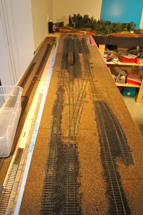
I'd agree the siding for the coal dealer looks a bit close (upper right hand corner in this picture), but it's deceiving as it measures at 1.75 inches per track center. A little tighter than I'd like, but I want that front of layout cushion.
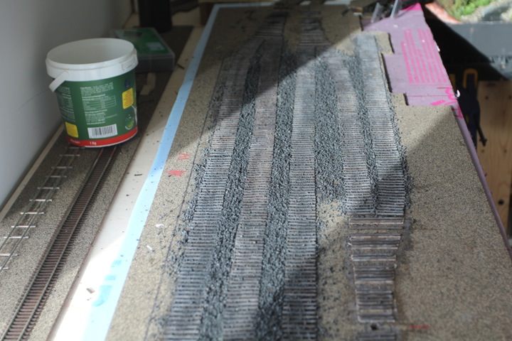
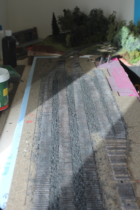
The ties are down - I should be able to start weathering them tomorrow prior to ballast.
What you also cannot see, is that the throwrod holes have been drilled under each as well, and I started the mass production of the bullfrogs needed for this section.
I meant to do more this weekend, but kinda got sucked into JMRI for a couple of hours...you know how that goes.
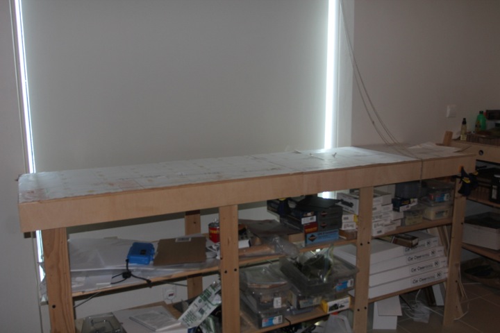
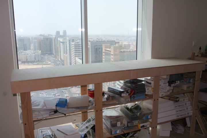
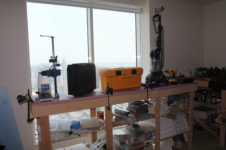
What you can see, is my new work island.
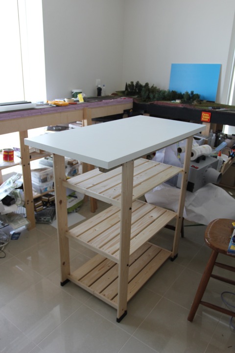
Shiny and new, the whole thing cost me $30. Astute readers will recognize that this is all Ikea, and GORM shelves, no less. Turns out that GORM has been discontinued other than a tall shelving set; fortunately I had four risers left over from before, and the shelves were on discount for about $4.50 each. The biggest cost was the top, which stands for me at a comfortable 45 inches (I prefer a standing workbench).
I found this necessary, as I had been using the very same sections I'm now completing as a workbench for the past two years - with that under construction, I found myself missing it.
And yes, the room has been (partially) cleaned and sorted - it certainly needed it, and during the process, I found some much needed things (like code 70 joiners).
Cleaning and organizing sucks, but it does have its benefits!
Just to prove I'm still working on this...
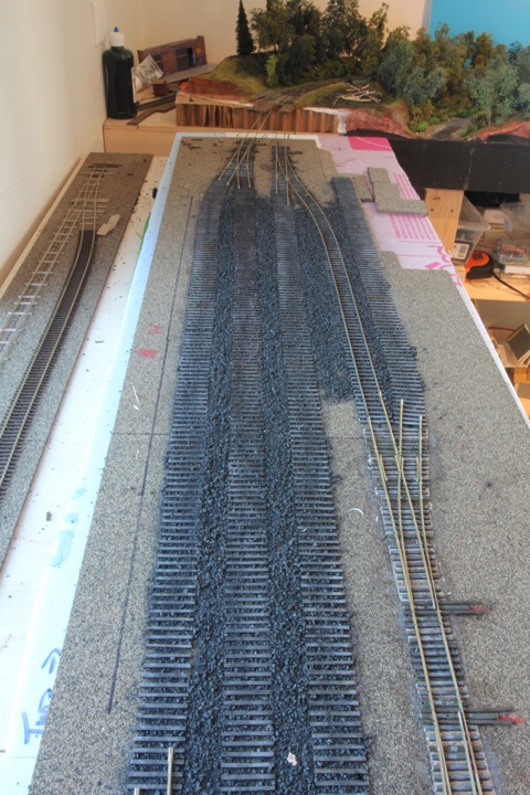
ballast!
and while that dried, I was able to make some progress on the fleet of bullfrogs needed for these modules.
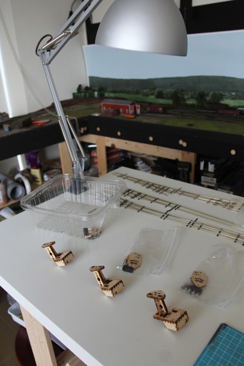
The only failure I've ever had from a bullfrog falls squarely onto my lap - it's easy, due to the way they are designed, to think they're solid just an hour or so after applying glue. I rushed that once, and had one fall apart once installed.
Now, I make them, and let the glue dry at least a day or more before final assembly and installation.
Just 7 more to go...
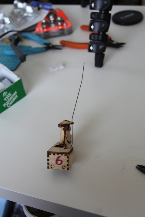
Well here's a whole lily pad's worth of bullfrogs, ready to go.
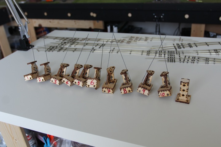
They're numbered as I the orientation for each was important; in some cases the turnouts are close together, or I need them facing for clearance of the module base.
You'll notice one of them isn't like the others. Number 6 is one of them old school bullfrogs that uses the magnets instead of the ball and spring. I have to admit, the newer design is better.
Here they are in their spots.
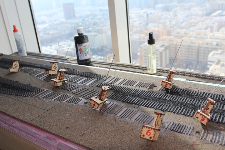
now, to get these mounted.
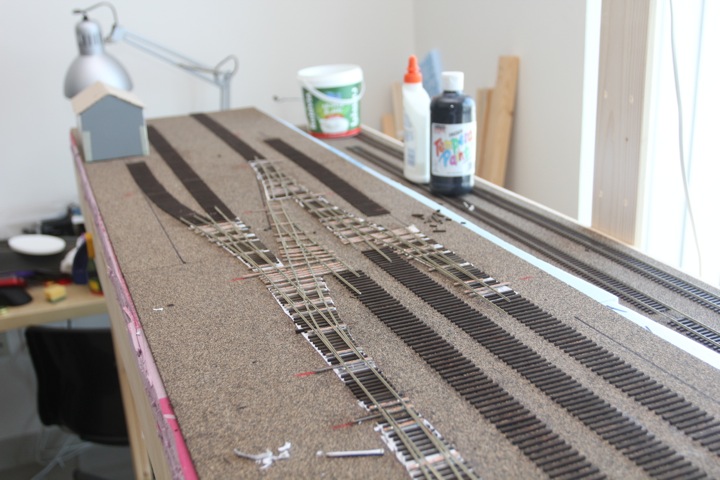
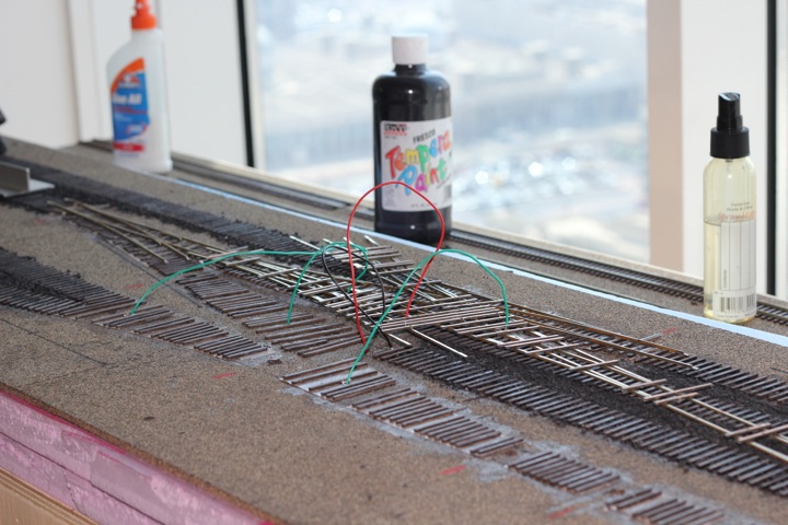
Spent a fair amount of time yesterday painting up the turnout sets. For those that are interested, I use the Floquil pens as a starting point, later one, once they're installed, I'll go over them again with a brush and fill in spots the pens don't reach.
Today - solder feeders, and than we're ready to start spiking!
Well it's the end of my weekend, and I'm pretty satisfied with the progress I've gotten done so far!
All of the turnouts are feedered, and spiked in place. I was also able to run a bit of connecting rail, and the short siding near the freight house.
Getting all the feeders in place can be tricky with a large turnout fixture like I've built; I like to run the wire down the holes, and than pull the turnout(s) into place from underneath. Here it is upside down, getting ready to pull.
And it worked pretty well (I solder the feeders to the bottom of the rail, so it's a bit harder to after the turnouts in place.
And here they are all spiked down!
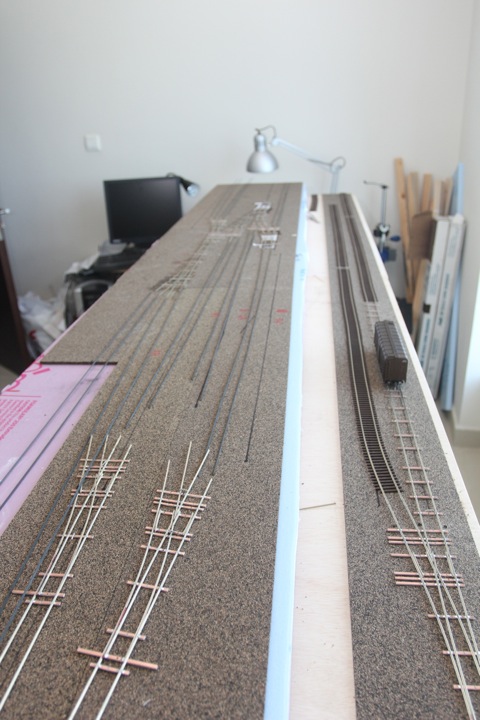
The first car!
Once the rest of the connecting rail is done, I'll pop the entire thing up on it's side to install the bullfrogs, and connect the electrical feeders to the bus.
Getting a little closer every day.
The track gangs have been busy. A couple of hours led to what may not look like a lot of track done, but I've hit the halfway mark.
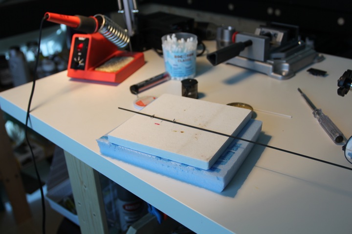
In case anyone is interested, I use this solder pad from Micro mark, and metal T-pins to hold rail in place while I solder feeders to the bottom of the rail web. This works well to hold it securely and hands free.
Finally, yesterday I was able to cut the slot needed for the DCC expansion slot. As I mentioned elsewhere, this was a challenge to do neatly without outdoor space or elaborate power tools - just a dremel, keyhole saw, and vacuum.
The DCC expansion port, while not mounted, works.
I fully expect withdrawals, Dave. I'll admit it - I like making track work. Folks say it takes a lot of time to hand lay, that flex is faster, but I look back at my progress since the fall of 2010, and I can't complain.
As far as being done, there isn't any way around that at this time, I've fully spent my track building supplies; I have two sticks of code 70 rail left, about a dozen turnout ties, and -1 code 70 rail joiners (I had to use a code 83 for one joint).
I'm looking forward to building some structures though, I have ton of rolling stock kits, and a few locos I'd like to work on as well.
Once the layout is done, I'll probably look at expanding it around the room to provide me with a continuous running option. I have a few ideas on that I'll share as I get closer to actually implementing it.
Well, its done. The last piece of rail, and the last spike. ![]()
that means tomorrow it can get flipped so I can mount the bullfrogs, and get wired up. Should have trains running within the week!
Thanks guys, with the track laid, there is a sense of accomplishment. It's nice to look back and see it finished. Benny, this layout was designed for operations, with the help of Bryon Henderson - so in this situation they overlap (hopefully) nicely.
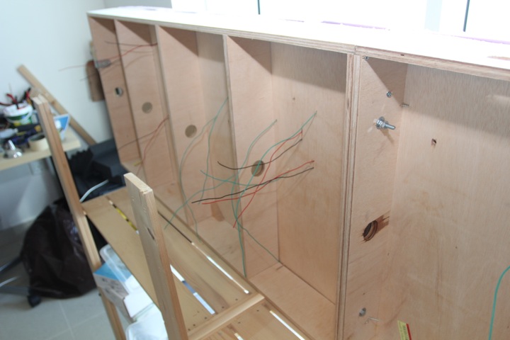
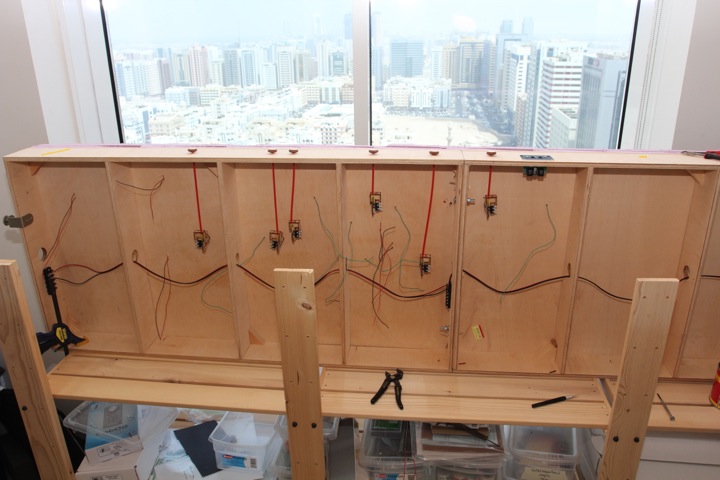
Post fourth of July holiday (thanks Jim!) I was able to spend a good 6 hours on the sections today. The results, were rewarding.
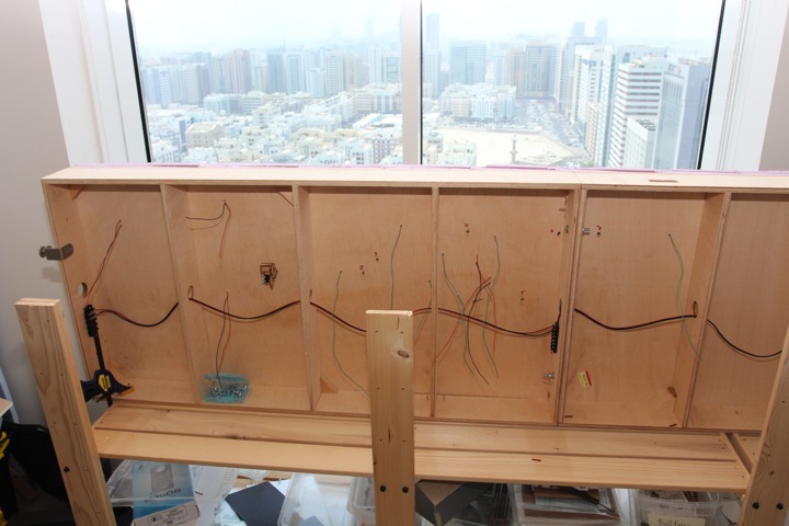
First up was flipping it over on its side. The bare second shelf makes a great place to work.
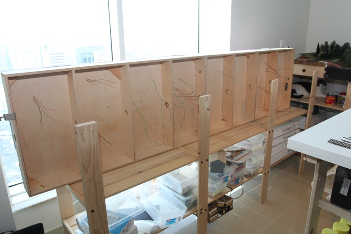
With it up on its side, the wires were streched out.
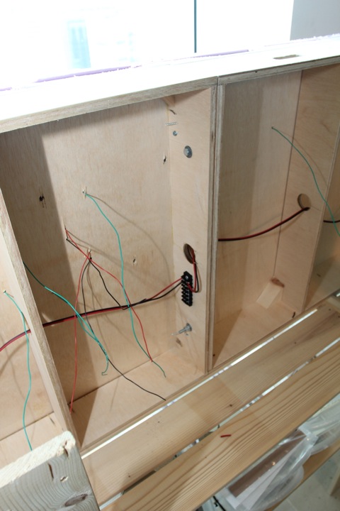
And the bus line was run. In the shot below, even though these modules are connected, I've put in the connection strip, and broken the bus at this point.
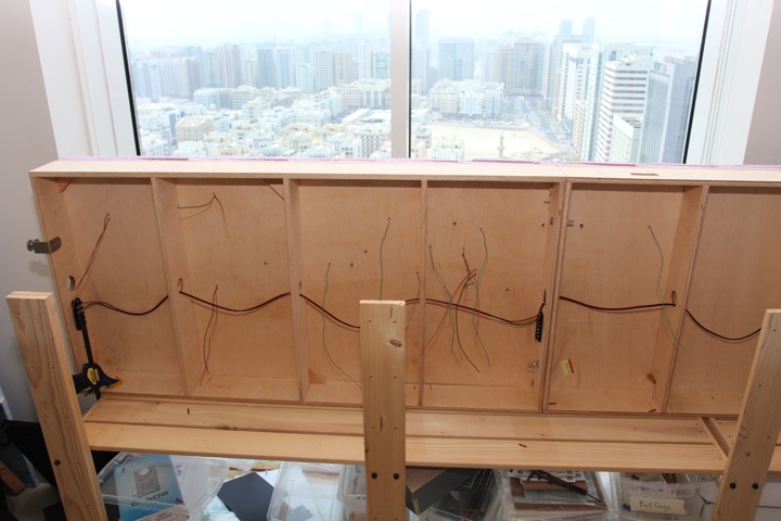
With that done, the bus was run across the entire 8 feet.
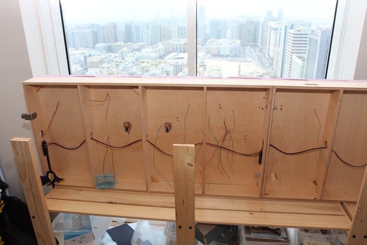
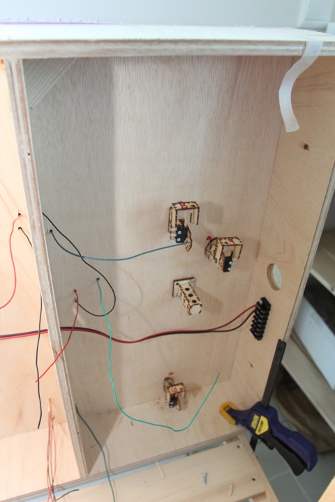
I started next with the bullfrogs. Folks may have their methods, but mine seems to work (for me). The first thing I do to mount a bullfrog, with the modules on their side, is pin the point to the upper rail using a clamp. Yeah, this is showing the lower rail clamped, I know.
With that in place, I find it easier to align the bullfrog on the other side for it's longest throw range. I feed the rod through (having a bright light, or in my case a window really helps) the hole, align in, and screw it in. Once it's tight, I check it's range of motion (freeing up the clamp of course), and adjust the bullfrog up and down as needed.
Bam, one done.
and two
and three, and four.
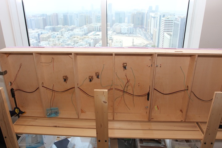
and five
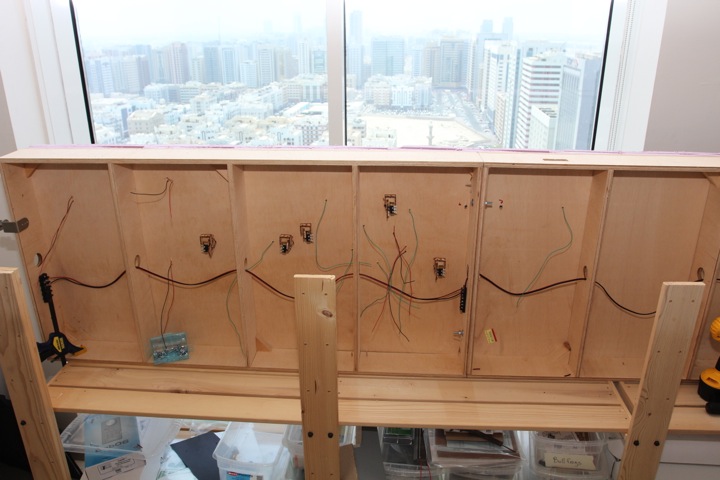
Critical Stop. If you've been reading this thread, you'll note that I pointed out bullfrog 6, one of the older style ones. Well it failed in it's installation. Completely. The older ones have a much longer throw range, but with a much less flexible mounting system.
This was combined with the fact that the throw path isn't vertical, I had to drill down at a slight angle to miss a brace. I forgot about the gap between the modules while in my orgy of turnout making, and it almost falls right on the seam. I was hoping it would work, but no go.
The result was it came out, and I'll have to order another, newer bullfrog. I do have a surface mount throw (caboose) ready in case I just can't get the under layout throws to work. You can see in this image how I tried to bend the throw to match the path.
So with six ignored, in goes seven.
on the far end, 8, 9, and 10 (plus the tadpole) were mounted as well.
With the bullfrogs mounted, holes in the fascia were drilled, and I began the installation of the pulls — first by measuring and placing the external (red) sheaths.
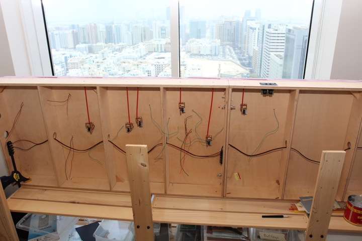
The inside pull rods were attached, and the knobs assembled.
On the other end, another example of how the flexible nature of the bullfrog pulls can be used to your advantage. You may notice the "modified" post; I realized when just to flip it back up, the pulls on the right would get pinched. 2 minutes with my trusty Japanese pullsaw, and we're good to go.
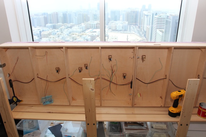
All of the wiring was completed; all feeders connected to the bus, as well as the microswitches. I haven't cleaned up the wiring yet, as I'll need to go back under to install the last bullfrog.
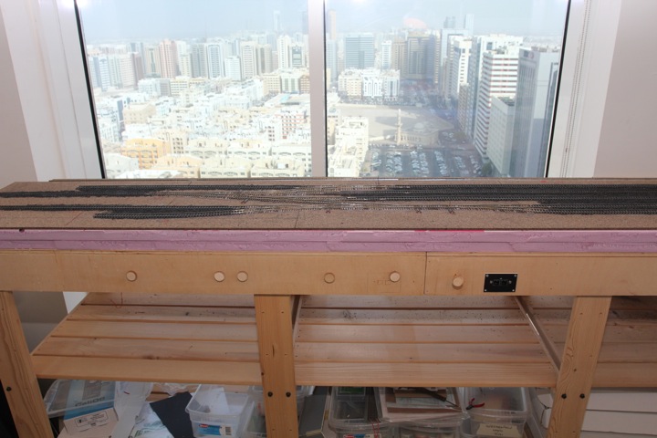
Flipped, and ready to run.
I began testing, and discovered an epic failure.
However I did it, I wired the frogs (all but one) the wrong way, and needed to flip it back over and move the wires around.
Phew! kind of a long day. Worth it?
Was it worth the work? Decide for yourself.
This is a poorly lit, pretty long and boring video; done on purpose at slow loco speed, so beware! (Kevin did ask).
I will say that I was pleased at how well the under tie electrical connections I made worked out!
I temporarily joined the module set to the rest of the layout; I'll be away for 3 weeks (back in the US), and wanted to find out what I needed before heading home. After testing, the list has been...informative.
I may get something else up this week, other wise, look for an August update.
Here's the temporary join - The rails are spiked to the ties, to hold gauge, but nothing is glued in. The modules are clamped to the rest of the layout.
And for the first time, I can actually have more than one train in staging! The staging tracks holds 10 car trains (with caboose and loco) each. I'll need to add a rear guard rail to keep them from falling off though. It's a hard floor behind there.
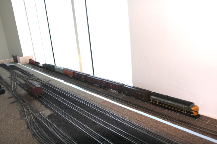
With the modules connected, I've been able to actually run the layout operationally as designed. So far, so good!
See for yourself - this video represents what would be a partial operating session (warning, the video is about 14 minutes long, and that's after a lot of cutting!), and the first train to run through to Barre!
I'd like to publicly thank Byron Henderson again for his assistance with the track plan design.
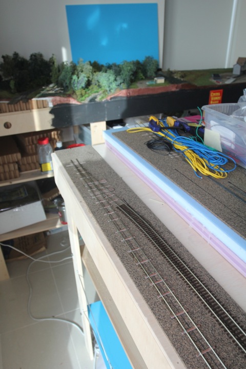
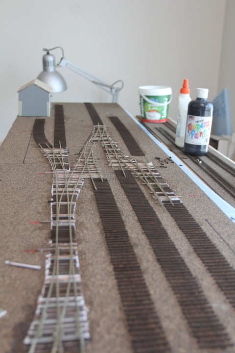
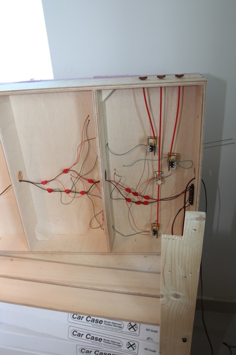
Progress on this section was on hold for many months, in part because it was working, but mostly because I was awaiting another Bullfrog from Fast Tracks. Thanks to the combination of the US and Canadian postal systems, the order never showed up, and after a long wait, the replacements did. This meant pulling the modules away from the rest of the layout (it was just clamped in place), and flipping it in preparation for the install.
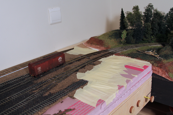
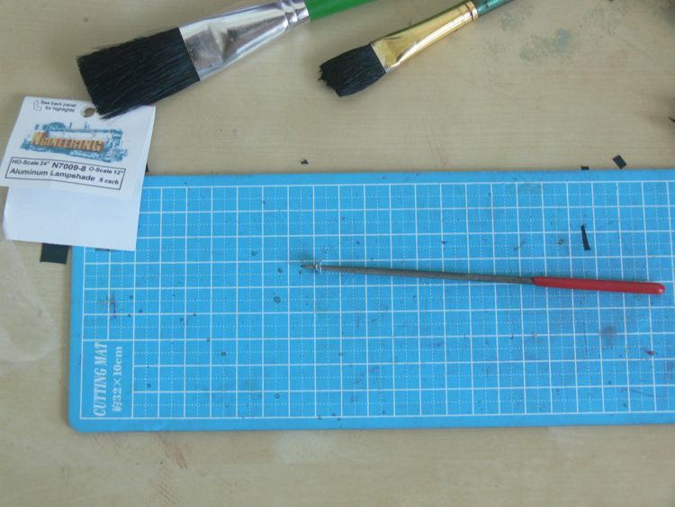
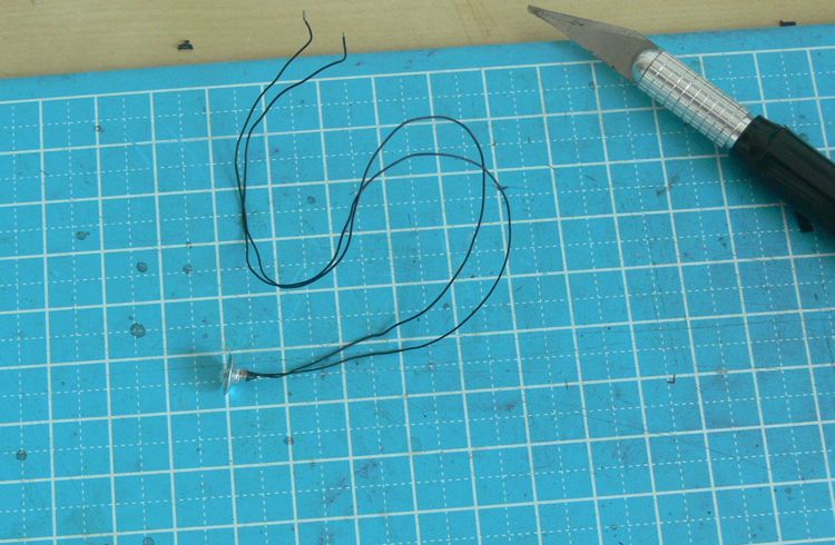
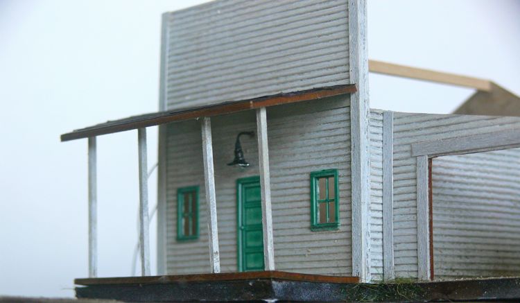
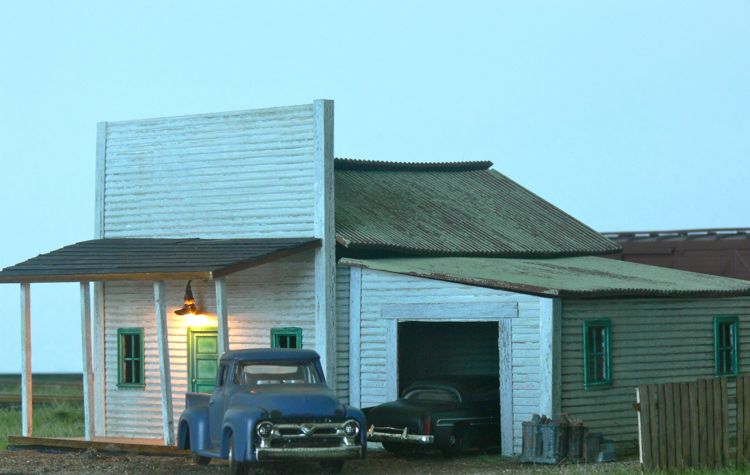
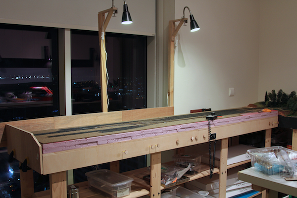
And installed it is. The modules went back on the support base, and a protective guard rail placed across the back near the storage tracks. Additionly, two lamps were installed to make switching easier.
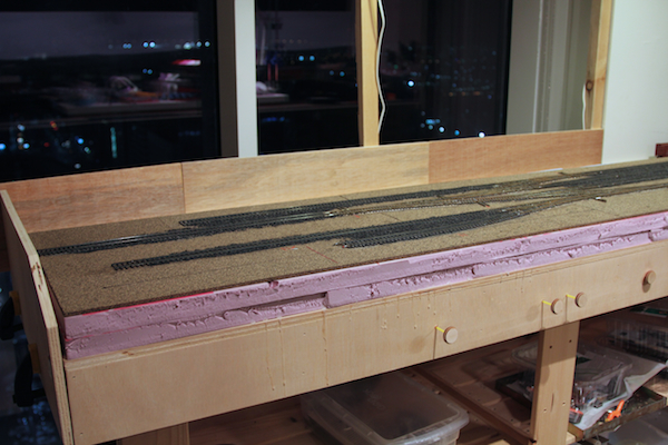
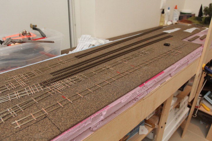
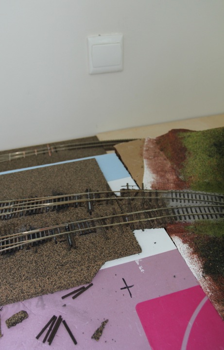
With rails re-connected, it was time to begin putting down the real ties. Here, loose ties were glued in.
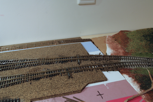
Once dry, they were trimmed, and the rails were spiked down.
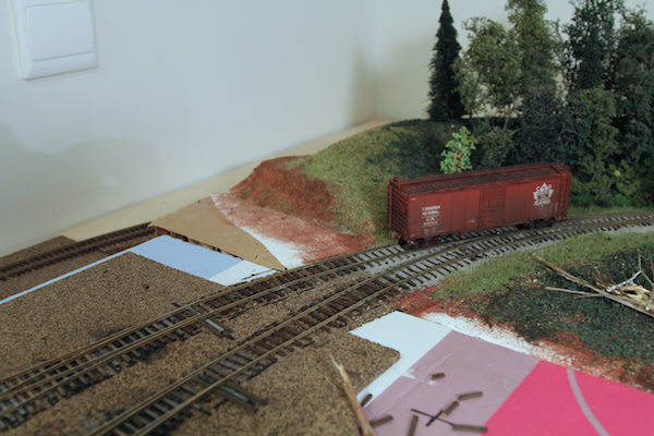
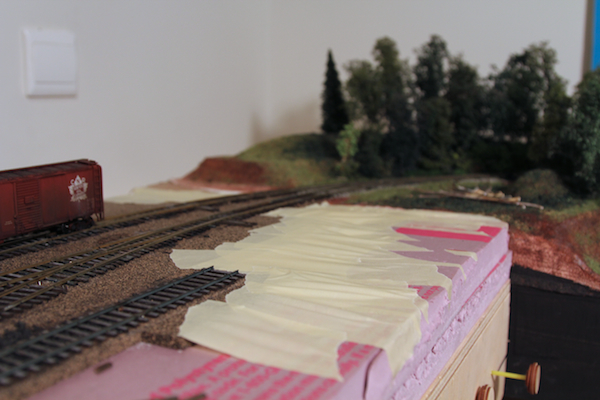
Next, was some pre-scenery dressing. Masking tape, stretched taut, makes a decent underlayment for plaster cloth.