Module 1
My goal here is to build my railroad, and provide, as well as I am able to, step by step descriptions and still photos of my progress. As a side goal if I can provide a guide (of sorts) to folks who are in a similar situation to myself. then that would be great
Note that the step-by-steps are as much for me as anyone else, I've been doing this type of blog work for over a decade now, and find it a great way to take notes while you are working, and identify problems later.
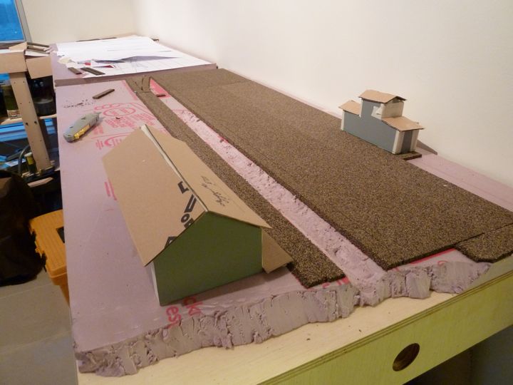
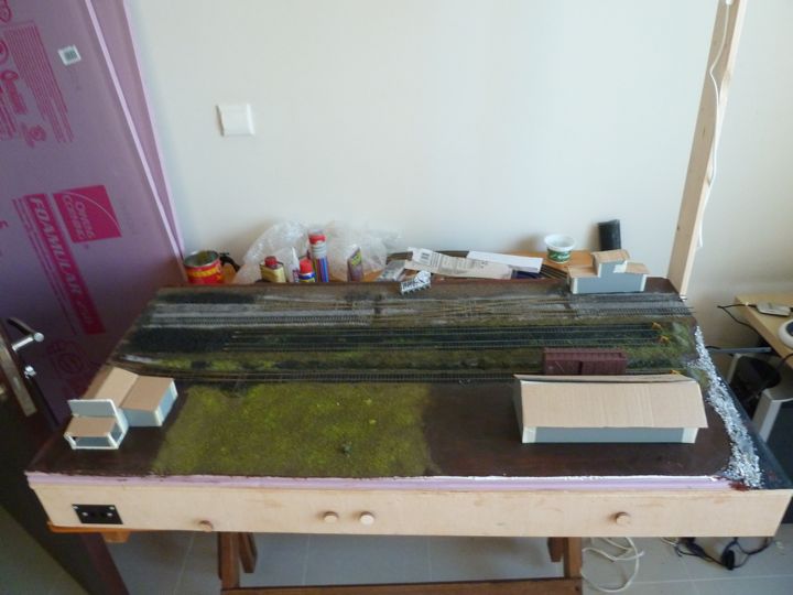
The first module is the one representing the far end of Montpelier Junction; there was no reason to work in one direction more than another, but I thought I'd start by the door.
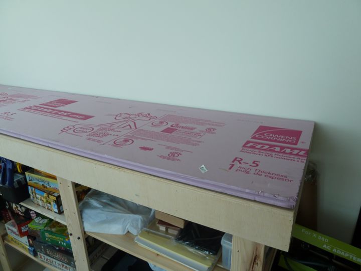
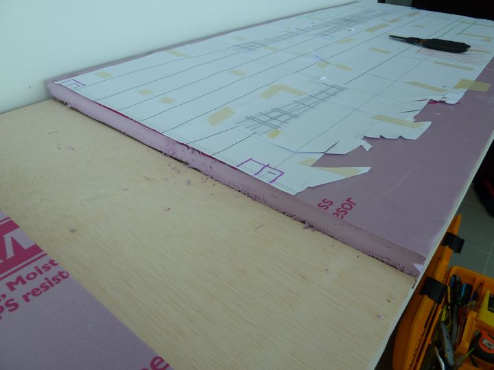
First up after removing the paper template was putting down the foam insulation board I brought with me (yup, shipped 3 sheets).
Next up was overlaying the template back on top of the insulation.
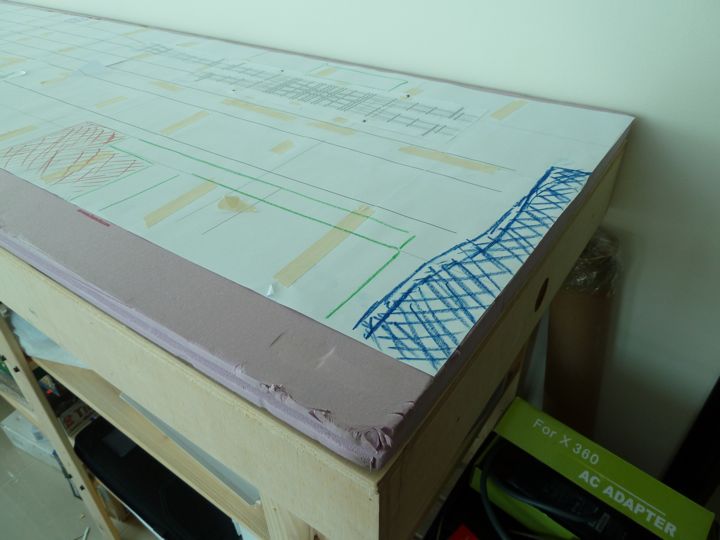
and now you can see why I marked up the template in Crayon. The river's edge of the foam was cut out.
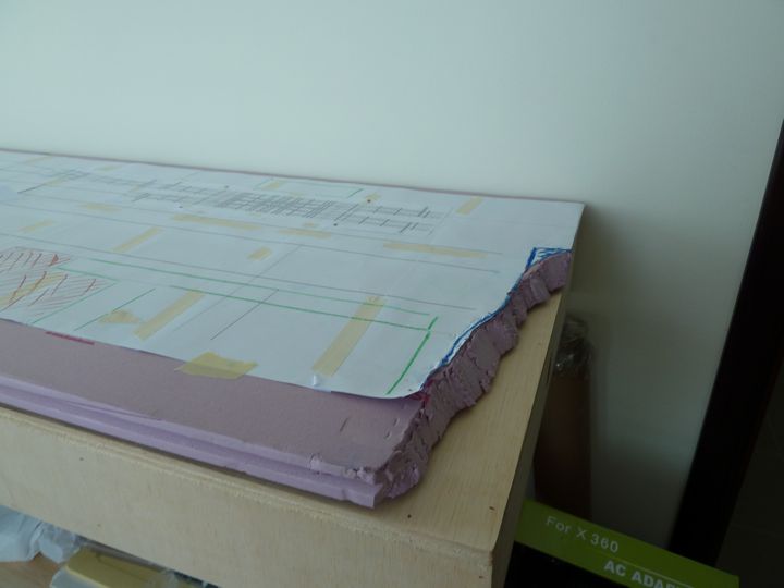
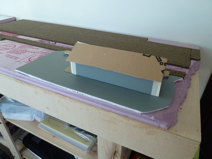
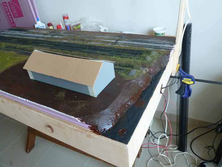
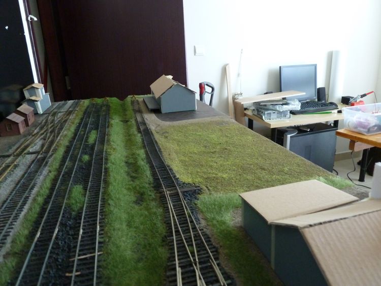
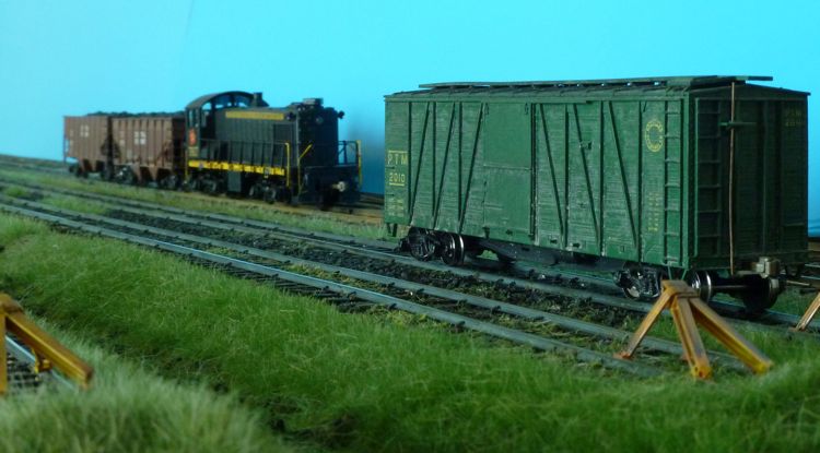
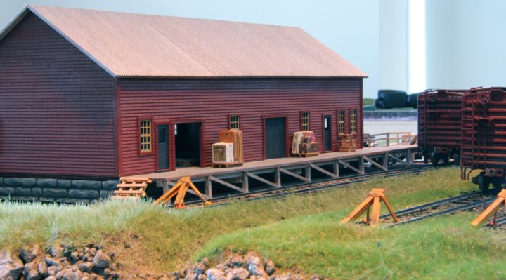
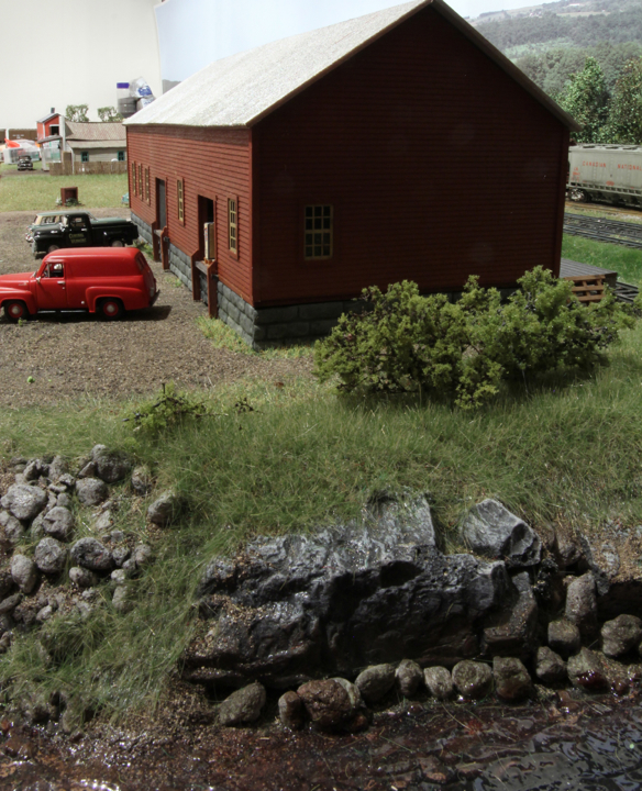
I'm hoping this will make a nice scene, with the freight house located on the water's edge.
On the other end, I cut the foam insulation board carefully, with a sharp utility knife blade, to module length.
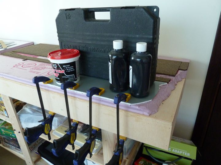
With that cut, it was time to attach (glue) the foam to the module top. A little creative clamping....(the toolbox is full)
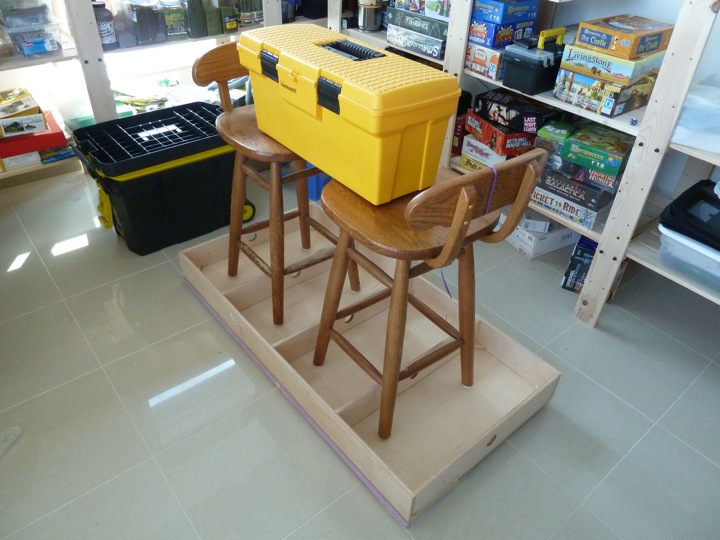
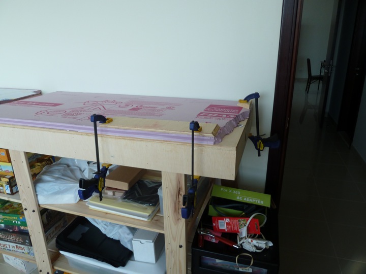
That though, didn't work - the foam insulation curled up on the edges. As a result, I injected more adhesive along the edge, and than clamped it down tight.
That tool box is my Fast Tracks Kit Box. I keep all my turnout fixtures in the bottom of mine as well as all kinds of solder, solder flux ,18" long pieces of rail, little wire brushes, a rail bending jig, extra soldering tips, & the point form tool + all the Point filing tools in the upper tray.
In the bottom I also have 6 bags of turnout ties 3 new Fast Tracks only crosscut Files and two Weller Soldering Irons about 400 PC Board Ties plus I keep the little billboards Fast Tracks sends with their fixtures.
My Box weighs close to 45 pounds so if you have as much stuff in your yellow tool box as me that should weigh down the foam top with no problem. I really like that tool box and wish I could find a couple more.
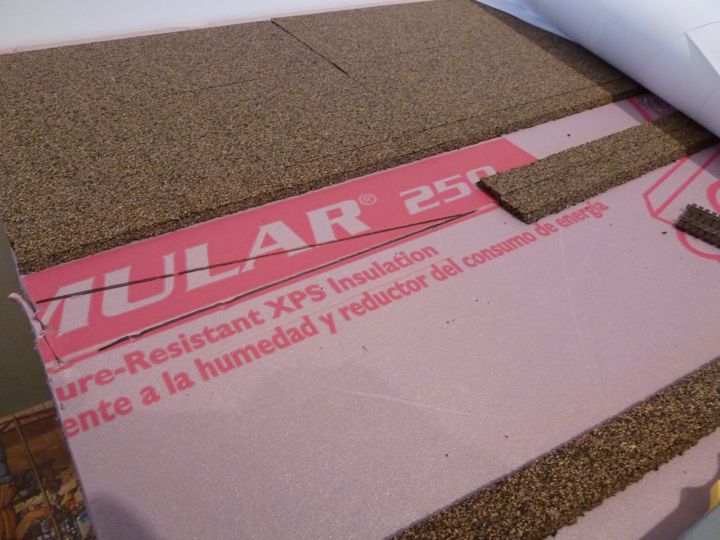
With the foam board now firmly secured to the plywood, the paper template goes back on and is aligned.
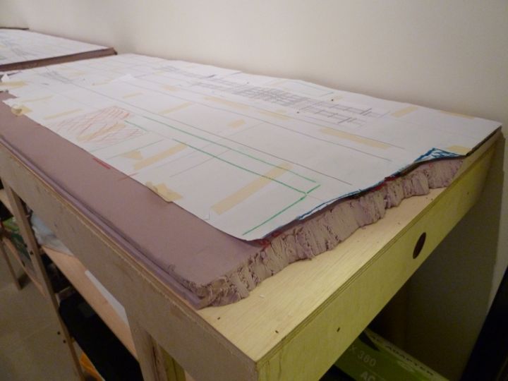
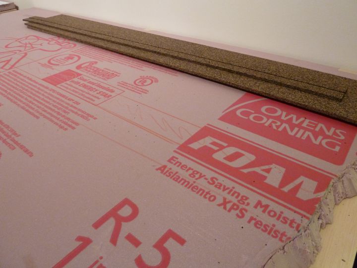
The cork underlay was carefully slid where I wanted it to go.
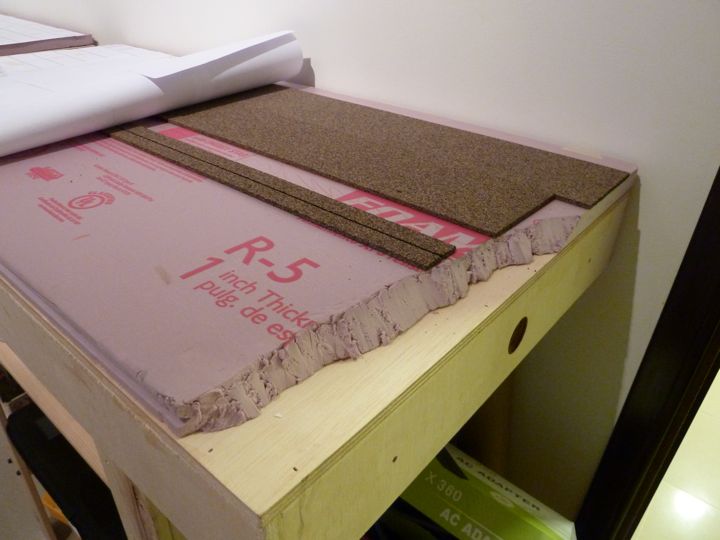
I marked the foam with a red pencil around the cork, so I'd know where to glue those pieces.
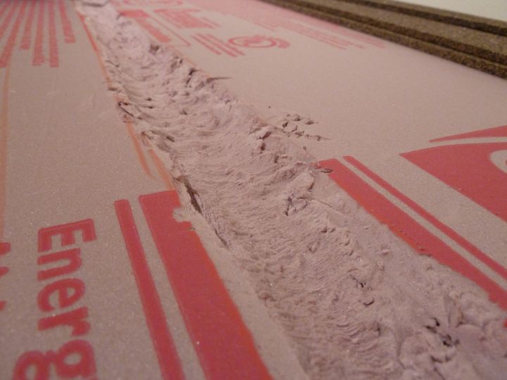
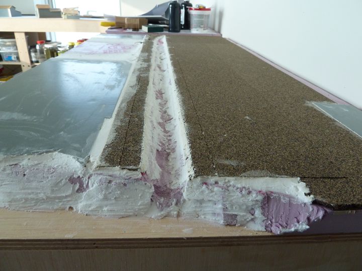
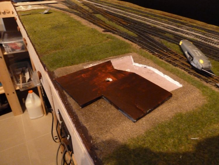
And then I decided to cut a slight drainage depression in between the freight house and yard tracks that empties into the river. Well not having the right tool was a pain, as I discovered that I left my rasp at home in the States.
I chipped away at it, but I needed to wait until I could find something similar locally to cut this out a bit smoother. I'd like to have the ditch dug before fixing the cork to the foam insulation board.
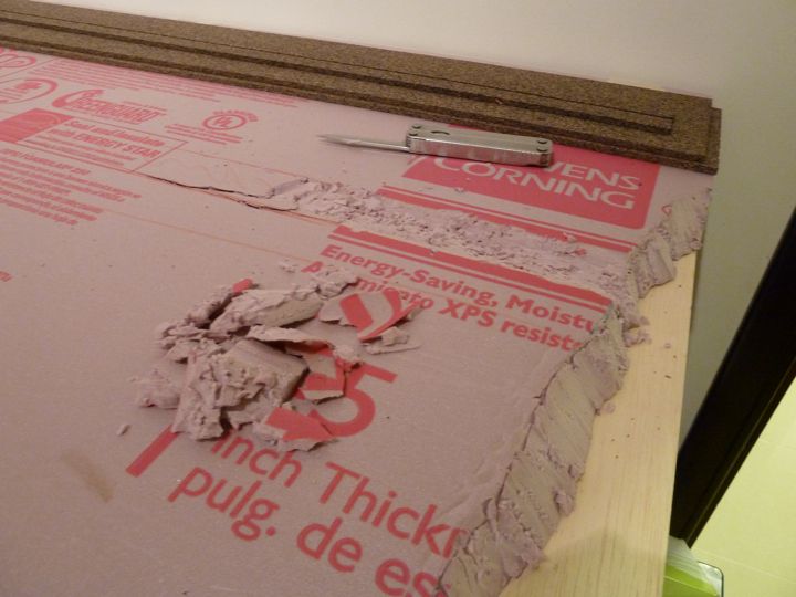
I get frustrated more by small things, than by large obstacles. The fact that I didn't have a rasp, and that getting one locally wasn't impossible, but a lot more involved than just running down to the local hardware/box store, was irritating me to no end.
I took a look at what I did bring, and I pulled out the Dremel. I wonder how this wire brush attachment will work...
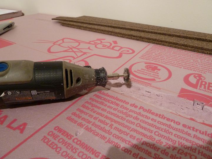
Really well, actually. It gave me a nice concave impression for the ditch (this is just a base cut, I will fill it with spackle or whatever I can find that's close), but boy did it make a mess. I ended up with a vacuum hose running right behind it, and that still wasn't enough to catch the mess.
One thing about modeling in an apartment, is you really have to stay on top of keeping it clean. I can't let materials just fall to the floor like I did in my old basement to be picked up later, you need to clean constantly.
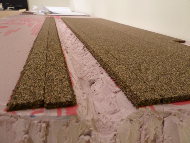
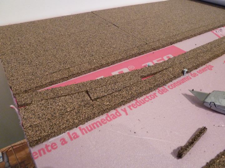
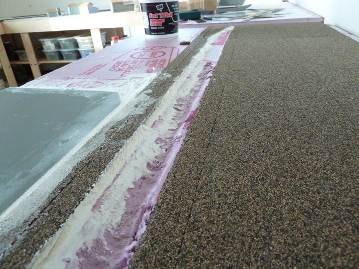
With the ditch now cut in, I went ahead, and put in the cork roadbed.
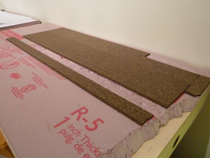
Running the beveled edges into the ditch should help enhance the slope.
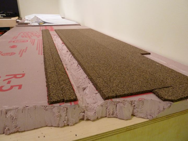
With that cork down, I finished off the module. Extending the main line ad track yard areas was easy, just measure and cut.
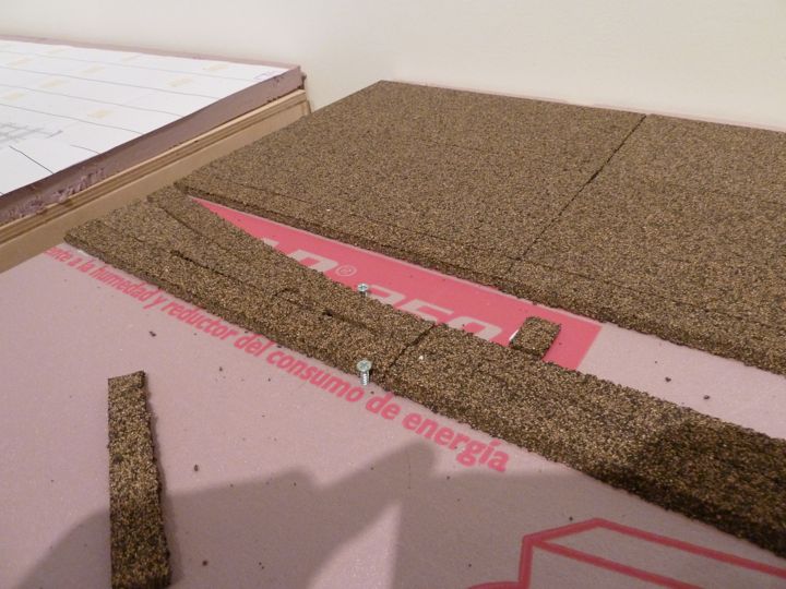
For the freight house lead, this module has a switch on the end. Using the paper template I punched through along the track center, and transferred the line to the pink foam.
I cut the single roadbed strips to match the outside of the turnout shape (based on the center line), and than filled the center with extra cork (left overs from the large yard pads). You'll notice a couple of screws; I've used toothpicks to hold cork in place while drying on foam board, but I didn't have any. The screws actually held well in this denser foam, and help keep the curve.
I was also able to mark the throw-bar position and add a pad on the side. I wonder though, would the prototype have put it here, or on the outside of the track?
With this in place, I can actually think about laying some track!
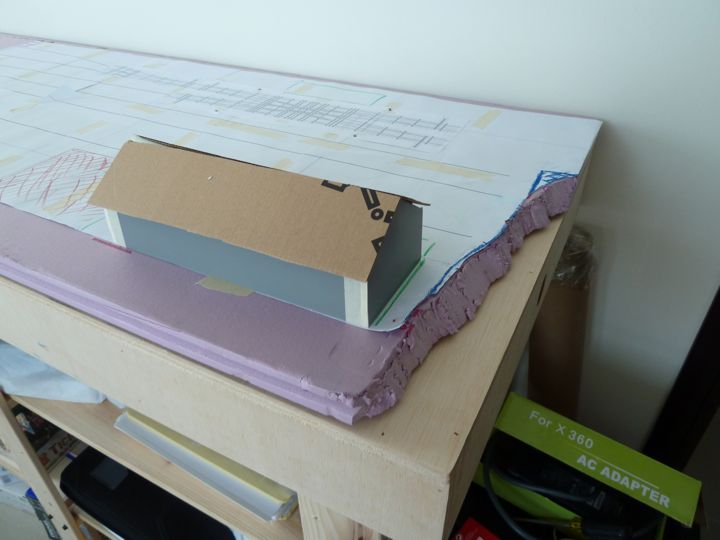
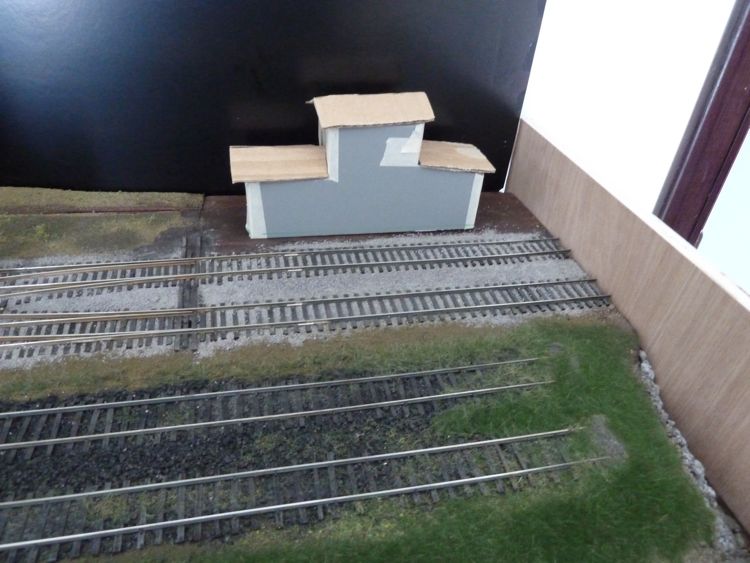
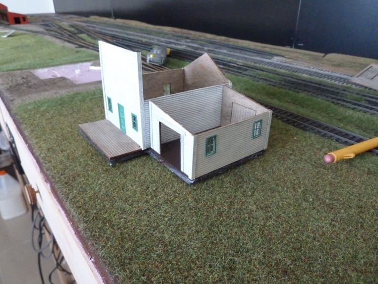
And another reason to do mockup's if you don't have the buildings in place...
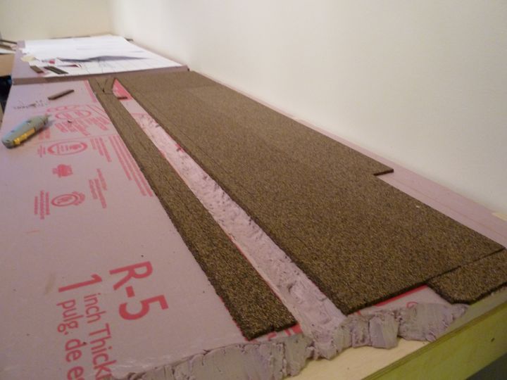
I picked up (finally) some sandpaper and a rasp(ish) style tool. That allowed me to work the edges of the foam, and the edges of the cork roadbed to a smoother, rounder shape.
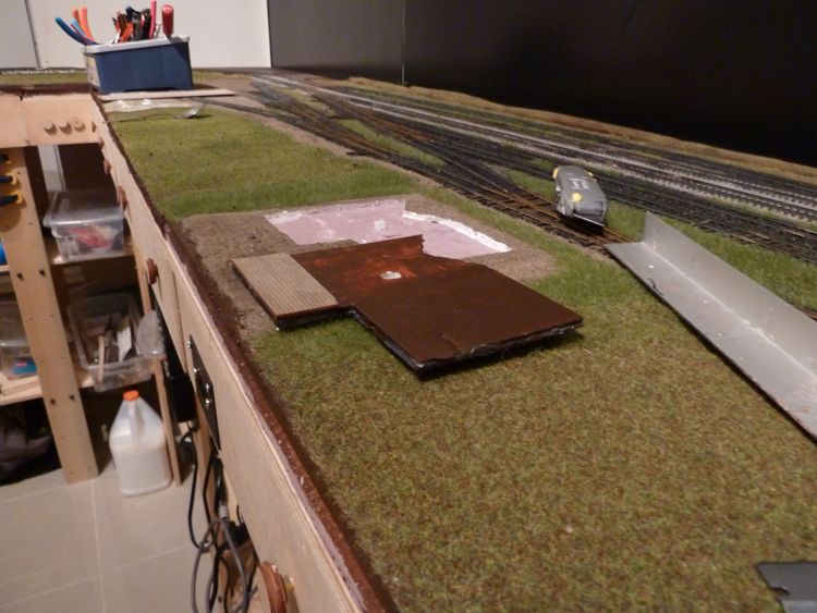
With that done, and the throw bar pad moved, I then cut a piece of extra foam board to level out the ground around the freight house. Another advantage of having the mock-up building.
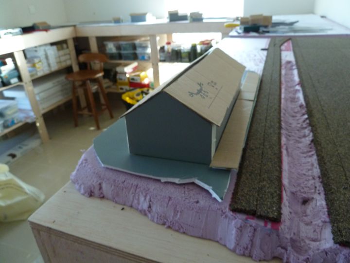
And, of course, the world's best clamping system.
Per adhesives, I've been shy telling folks, but the truth is the adhesive I've used so far (from the pink foam to plywood connection, cork to pink foam, and now foam core to pink foam) has been straight up white glue. I'm hoping it doesn't come back to bite me, but so far, so good.
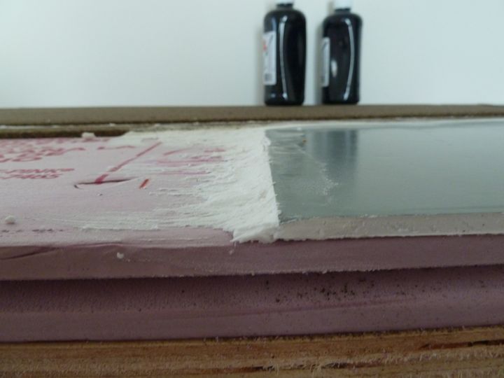
Lightweight spackle, not my preferred choice of materials, but one I could find. Sometimes, that's just enough.
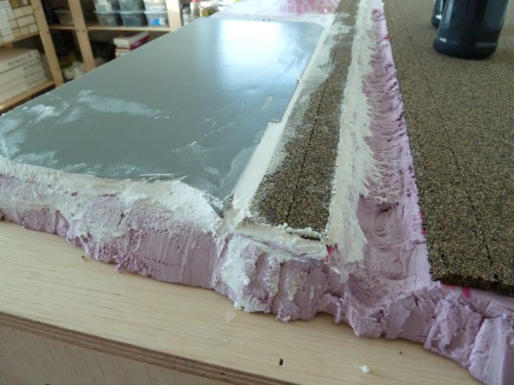
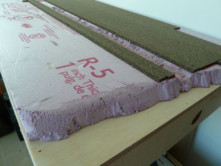
This shot shows the base of the slope that I want to build out, I'd like for this to be a very gradual transition. I'm going to guess that it will take probably 3 coats to get the look I'd like.
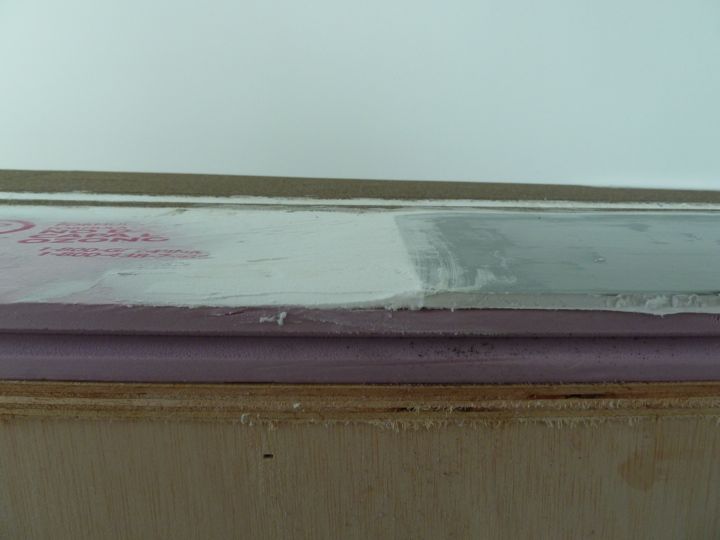
I put down another coat of spackle, and this area is almost ready for a coat of base paint.
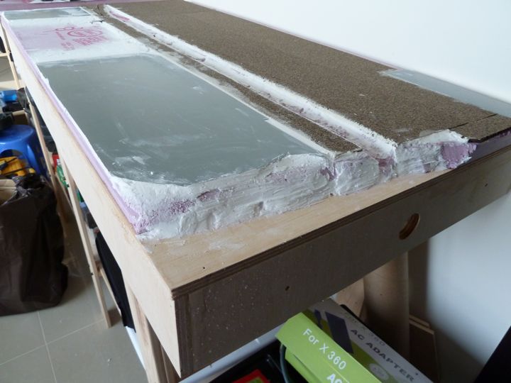
You can see in this shot how a second coat clearly improved the slope.
I put down another "pad" of foam core, not sure what for, but at least it will be there and provide some variation in terrain height.
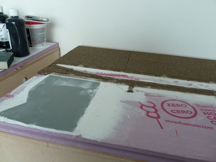
and the ditch was smoothed out a bit.
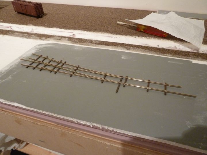
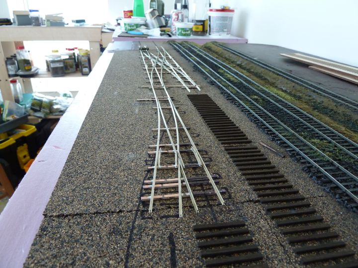
I'd been chomping at the bit to get some rail down, and it was finally time. I like to start with the turnouts in an area before laying simple track, so I thought I'd begin with a simple number six right hand turnout.
Boy did I f@#^ this one up a thousand different ways.
I had not done a Fast Tracks turnout in well over a year or more, and I just dove in, relying on what turned out to be a less than functional memory.
Rail cutters snapping, the stink of flux, hot solder slinging around the room, and after an hour I somehow ended up with this. Can anyone spot the first major failure?
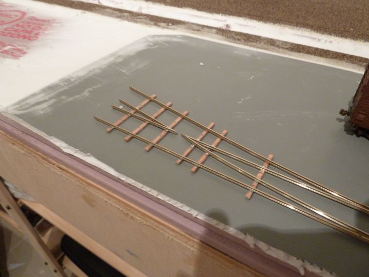
I really don't want to talk about it, suffice to say I went back and looked at the printed templates I was using on the layout, and smacked myself in the head. Than I realized that instead of the number 6 point form, I had been using the number 5.
At that point I washed the turnout, rinsed it, and walked way for a cold beer. Clearly I was having issues.
After dinner, I went back and took another look. As you know materials are precious, and while I can afford to scrap a piece or two, I'd prefer not to. Than again, I'd like to have my track work as bulletproof as possible. With that in mind, I dug back into it.
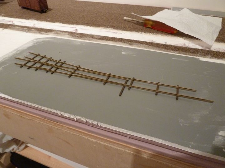
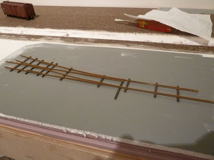
Looking at the template, there is a gap cut before the frog — it would appear that I could simply cut the offending piece off, and build the rest of it back up. Which is what I did.
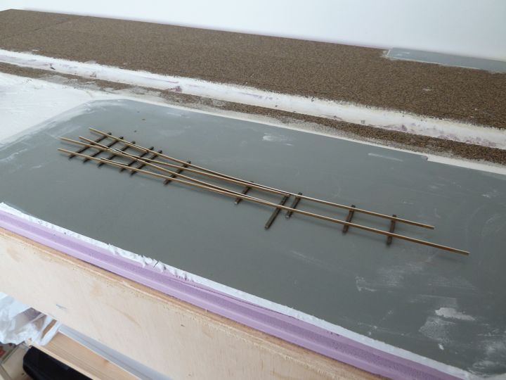
The results?
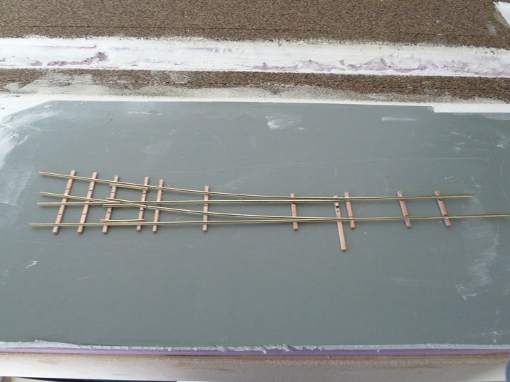
The good news is an NMRA gauge indicated that all was with acceptable limits.
I still need to gap this, solder on some feeders, and test it a bit more ruggedly. I am prepared to ditch it if shows any issues, but overall, it wasn't a bad rescue.
I'm just VERY thankful that I didn't start with the double crossover!
I'm not sure if I've shared this, but not only are we in an apartment on the 22nd floor, but we basically don't have any windows that really open. Yeah, I know. This means painting is a challenge. I was kinda planning on this, and instead of painting the Fast Tracks turnouts with the airbrush, I thought I'd try the Floquil paint pens. I ordered two sets before I left, and had them shipped in the goods.
Sorry for the bad pictures here, I shot them in the evening.
Here's the turnout with tie brown on the ties
And rail brown on the rails
A final coat of rust on the rails
Finally, after it dried overnight, a quick rub with a bright boy to polish the rail tops.
Overall I'm very satisfied with the markers so far, sure they couldn't get everywhere, but the overall effect is great, and has minimal cleanup and environmental impact.
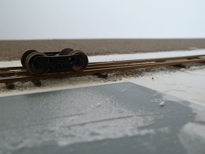
I gave it a quick test with a pair of trucks, and re-checked the electrical isolation of the tracks, one more time, just to be sure.
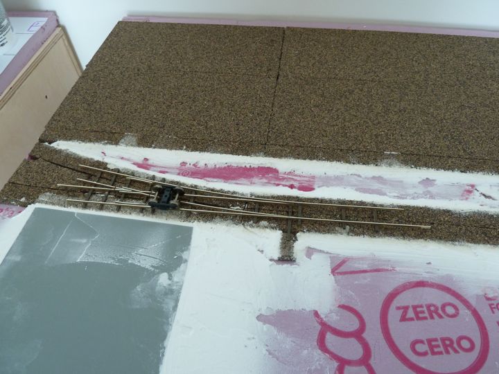
Here's a closeup of the rail. Not too shabby.
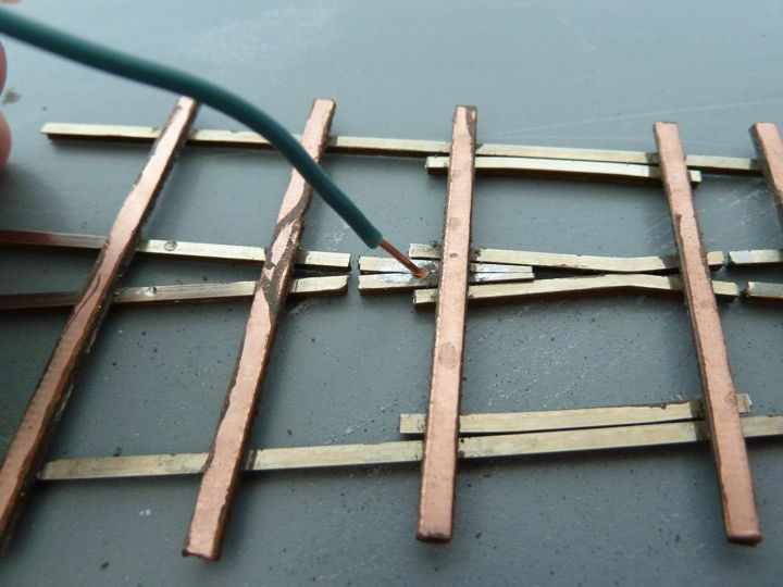
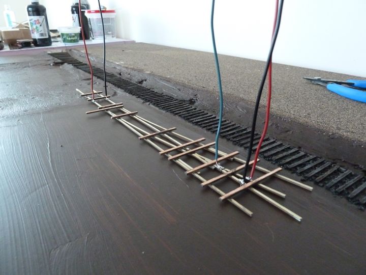
Flipping the switch over, I drilled some holes into the bottom of the rail for electrical connections. This one is for the powered frog
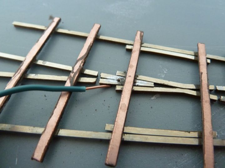
This should be a nice solid connection.
With those drilled, I kept the drill spinning, and drilled the hole needed for the throw. I used a 5/16" drill bit to get through the cork, 1 inch foam, and 1/4 plywood.
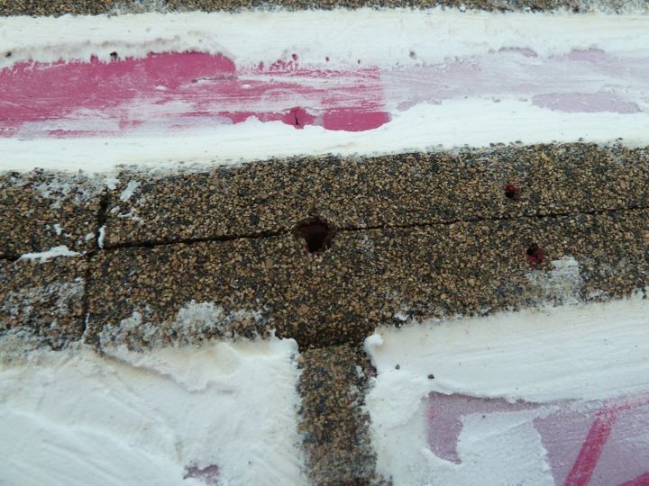
On the bottom, well, as luck would have it, I hit one of the cross pieces.
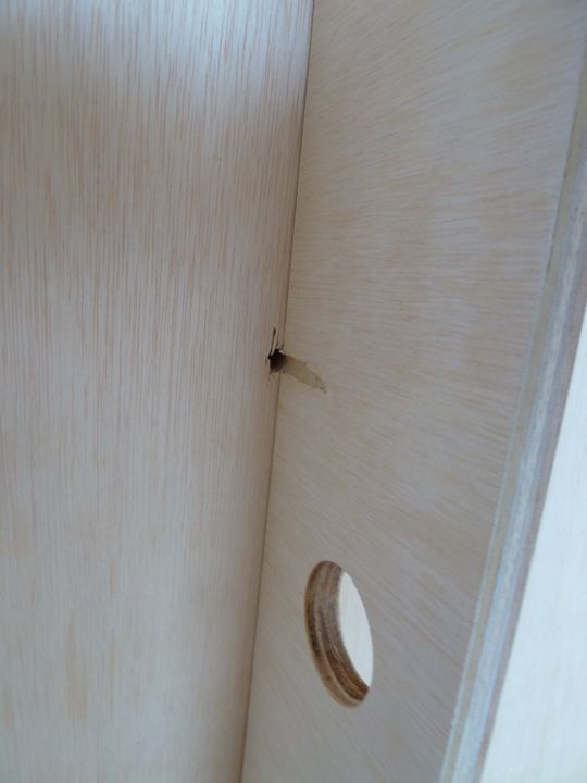
Figures. While I can move or cut these out, I'd prefer not too, for obvious reasons. One of the huge advantages of the Bullfrogs is getting them lined up to work isn't that tough, and in this case, I was able to flip it around and feed the wire up without too much bending. Heck, there was even room to mount the darn thing.
It's a tight fit, but fit it does.
So will it work? That's a bigger question.
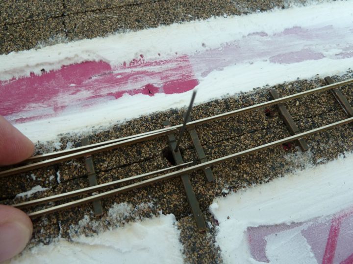
The rod is nicely centered in the hole
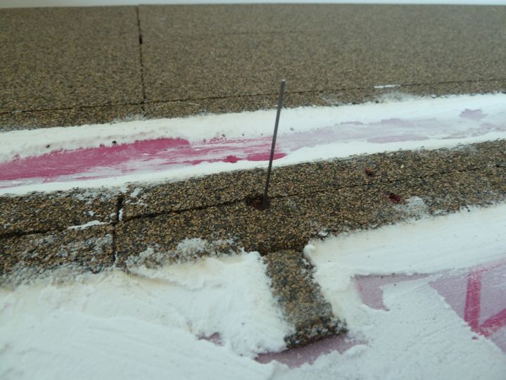
Which provided full throw on the points in both directions. I think we have a keeper.
That install almost went too easy, so I'm expecting a problem somewhere.
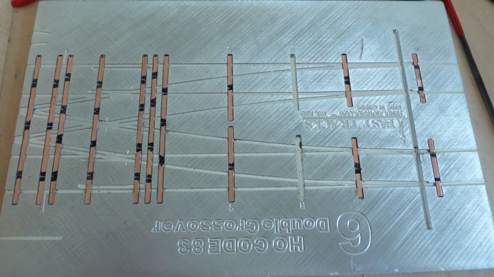
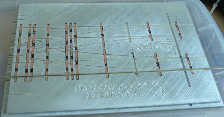
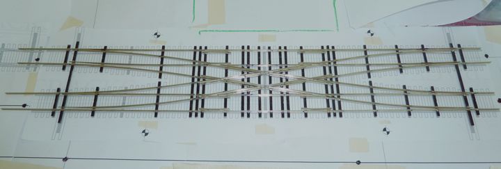
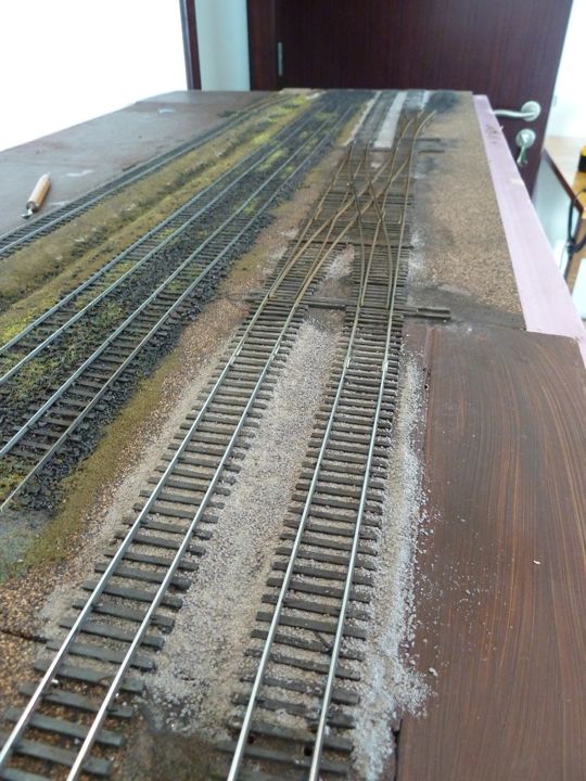
Double Crossover
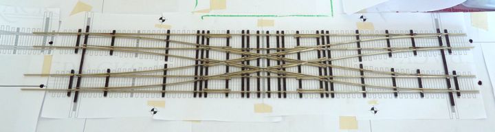
With that working, it was time to charge forward and dive into the Double Crossover.
This is going to be a pretty big challenge, so I thought I'd detail it as much as I can remember to. First up were the ties for this half of the cross over; I use (I think it's Dan's trick) sharpie around the gaps to keep the solder from wicking in.
The first stock rail. Note that I had to guess and cut the other end of the stock rail prior to soldering this one in.
Once the stock rails were soldered in on this end, I went ahead and cut the frog point for the diverging routes, including cutting out the rail web for the points.
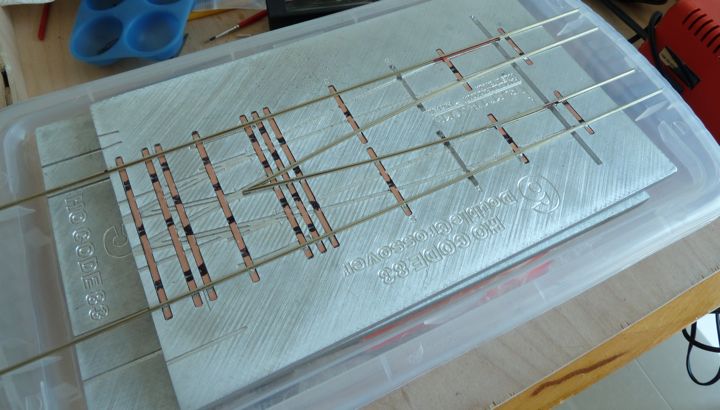
I went ahead and started putting in the points as well. First were the outside points.
 Than the inside one. Instead of having these flow into the frog, I simply cut them where the gap on the plans indicated.
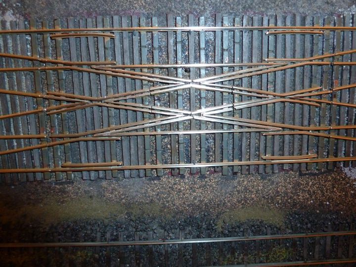
Guard rails were next, mostly to help stiffen up the entire skeleton
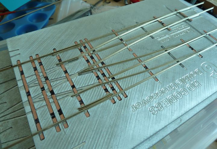
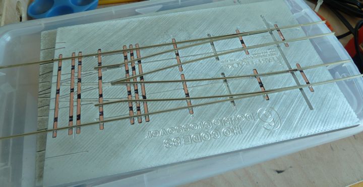
Finally I put together one of the frogs. After two tries, I think I'll be pulling it back out though, It actually ended up a bit short according to the plan, even though it "fit" in the jig. It may not be a big problem, but I'm unwilling to risk it, and would rather pull it out and redo.
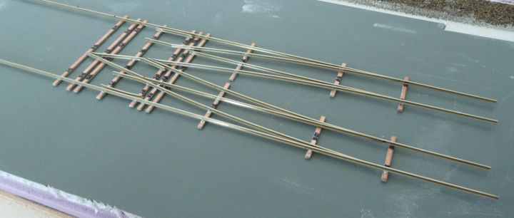
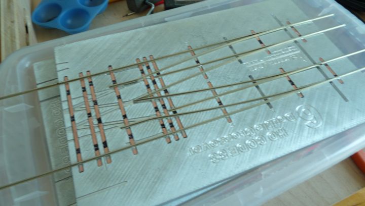
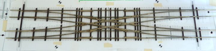
I got the other end mounted, the points and first frog and guardrails in, and removed the offending frog. This thing is huge.
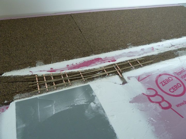
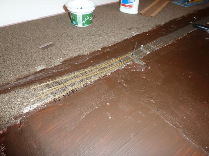
For a change of pace, I picked up a small(ish) pot of burnt umber (it was 10x as expensive as what I've paid for a large bottle at Micheal's), to get rid of the pink foam
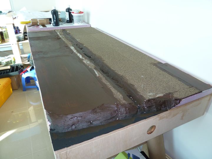
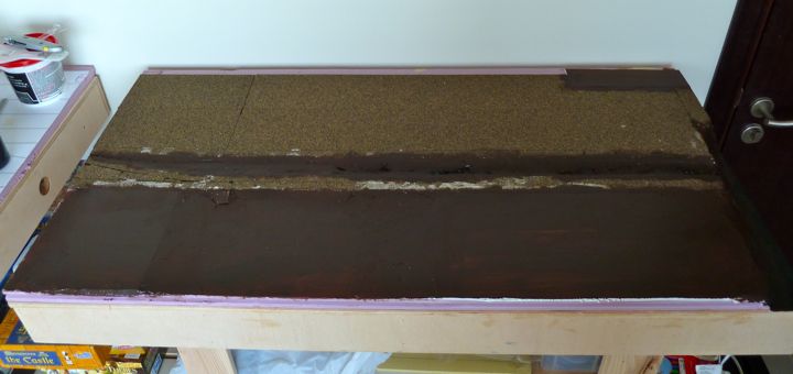
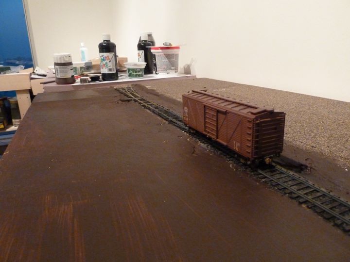
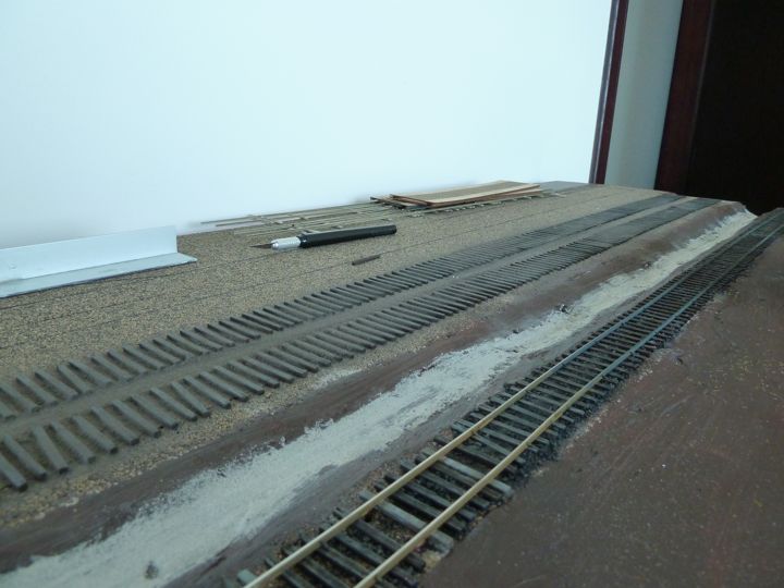
And, better yet, I can start putting down some ties........which than means rail.....which means I may see some actual train movement before too long!
The front siding was the first to get it.
You can see I'm using the Micro Engineering pre-weathered (more like pre-stained) ties.
I went with the pre-stained ties as again, I don't have the outdoor space (read ventilated) space I used to to do this kind of thing myself.
I'm intending on softening the color of these up a fair bit through dry brushing prior to ballasting. We'll see how that works out.
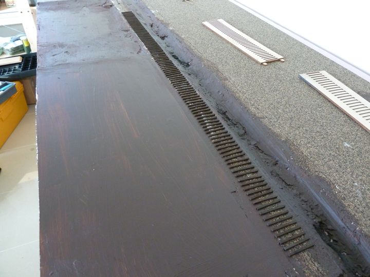
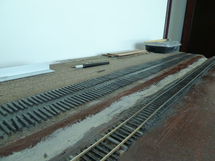
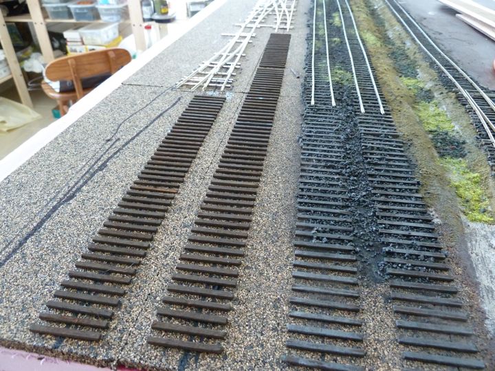
It's been a few days, but only because some of the time between stages here can be a bit long. I normally put down a run of ties, and let it dry overnight before continuing, so this develops into a bit lengthier process.
More ties down around the turnout.
Once they were dried in place. I cut them to fit.
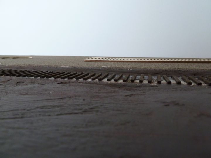
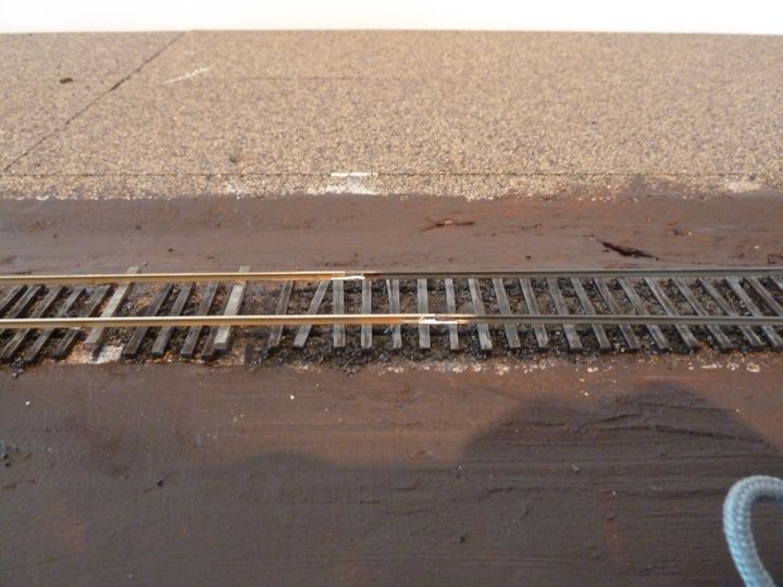
Back in daylight, the ties were hit with a gray dry brush to lighten them up, and than a basic coat of cinders went down.
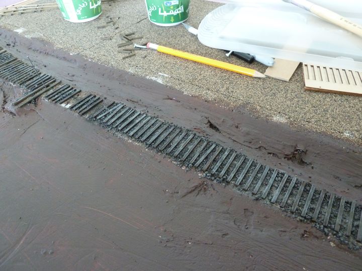
Some of these cinders were bigger than I'd like, but I've discovered that they are from real cinders. and as a result, the larger pieces.
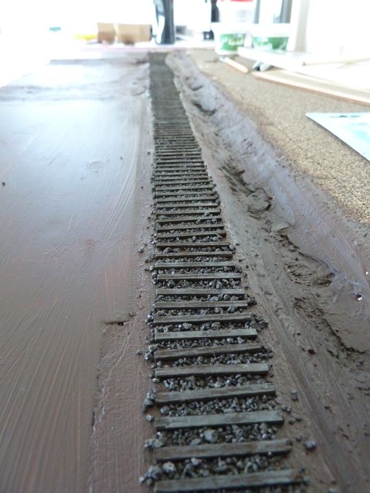
I've also had a real problem getting Isopropyl alcohol, I finally found a anti-bacterial solution at a local pharmacy that is 70% IA, enough to act as a wetting agent. The other 30%? Lets just say it has a nice smell.
I started brushing away the loose bits after the glue and water mix dried.
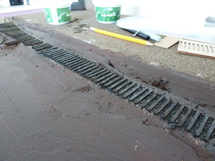
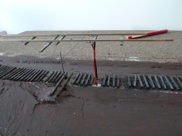
Now with this down, I'm ready to lay some rail once I get the turnout wired.
I've added a lot of feeders to this, as I don't intend on wiring up any others for the siding (I'll solder the connectors instead). The green wire is for the frog.
Here you can see the feeders as I slide it into the holes. My plan of drilling holes to set the wires in failed; I drilled and drilled with my bit in the Dremel, mounted in the drill press mount, but grew afraid I'd break the bit (replacements aren't easy to find). So instead I fell back to what I've done before; solder them to the bottom of the rail.
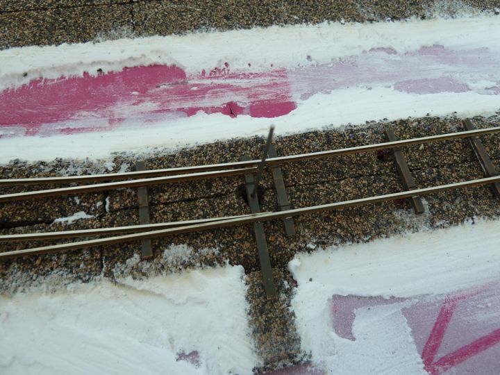
With the turnout in place, I hooked up some longer rail for the siding.
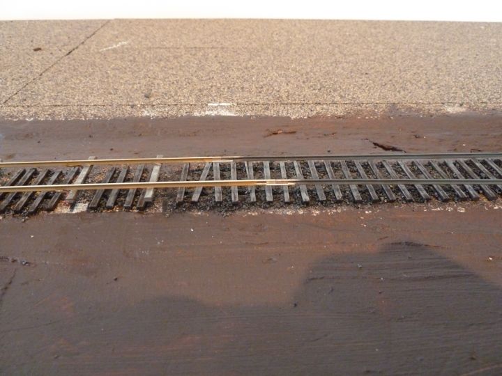
And soldered them together. Note I buff the weathered rail clear with the Dremel wire brush before soldering.
Spiking came next.
I like to walk a car down as I spike, I know it's not as accurate as a gauge (although I use one of those as well), but it's more fun.
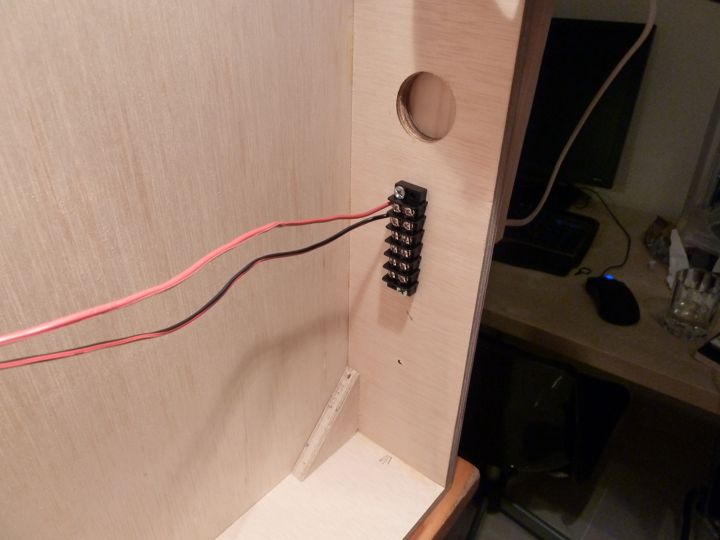
Next, was wiring, and one of the real advantages of doing this "module style". Up on the bench you.
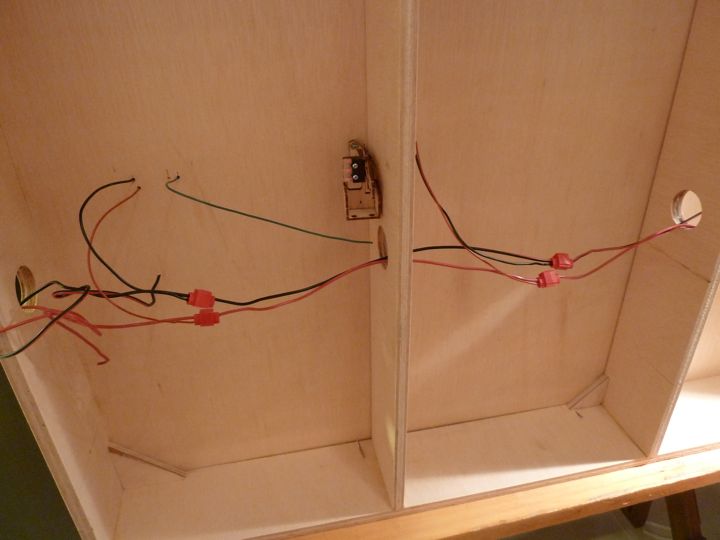
I ran a bus line, and tied it into the connector on this end (I added feed wires for the PowerCab later).
And on the other end, the turnout leads were "suitcased" into place. The frog wires were left out for now, as I wanted to test the other connections first.
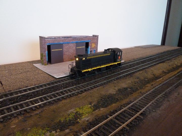
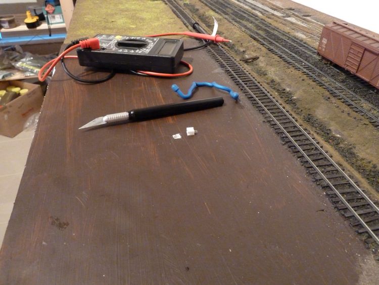
So far, what's the result? I couldn't stand it, and hooked up the PowerCab. Being not a total fool, I did check the rails with the multimeter, and came up with no errors before I turned on the power and put a loco on the rails.
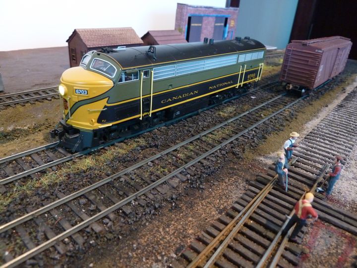
Lights! Power! Action!
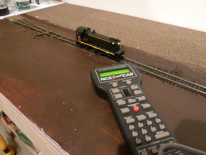
it's been over 5 months since I've been able to run a loco even this far....having it working is a nice change.
One real problem though, that I identified last night. Apparently when I mounted the other turnout, I used the wrong pair of pliers, and my rail nippers took a hit. I didn't notice it at the time, but there is a nice round notch in mine that I had to work around with the double crossover.
So.....I placed an order through Fast Tracks for a replacement. While I'm ordering.....I threw in a couple of spare tools (I have a lot of track to lay), a couple of extra bullfrogs, and a single frog juicer (for the crossover) to make it worth the shipping cost. The guys at Fast Tracks are quick to ship, so we'll see how long it really takes to get here, and through my ARAMEX delivery box.
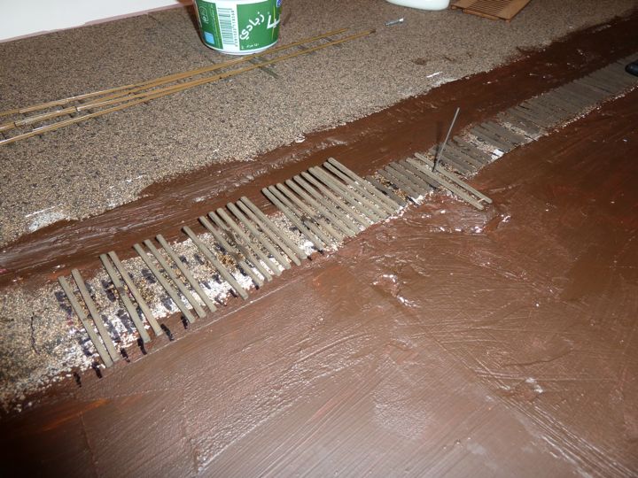
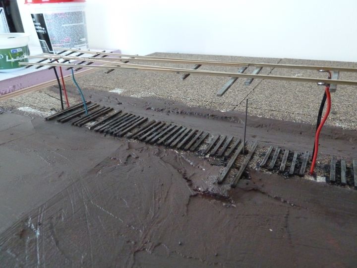
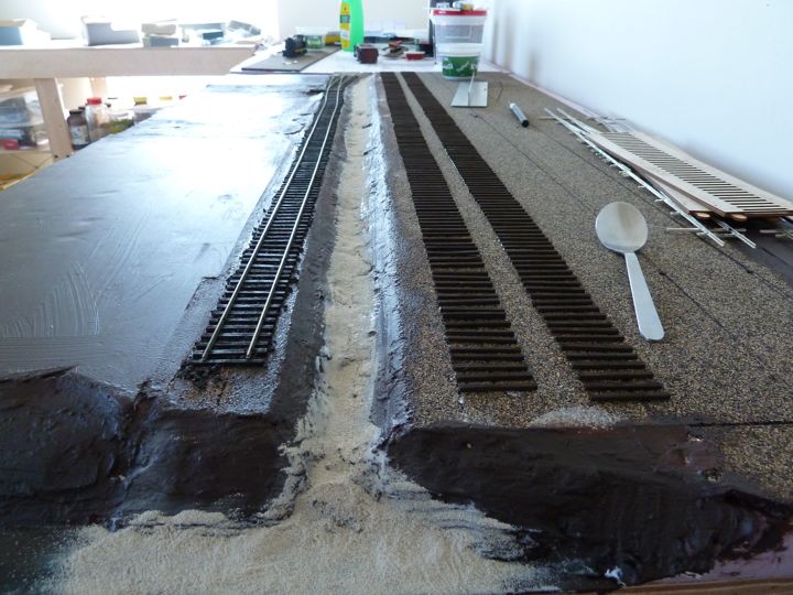
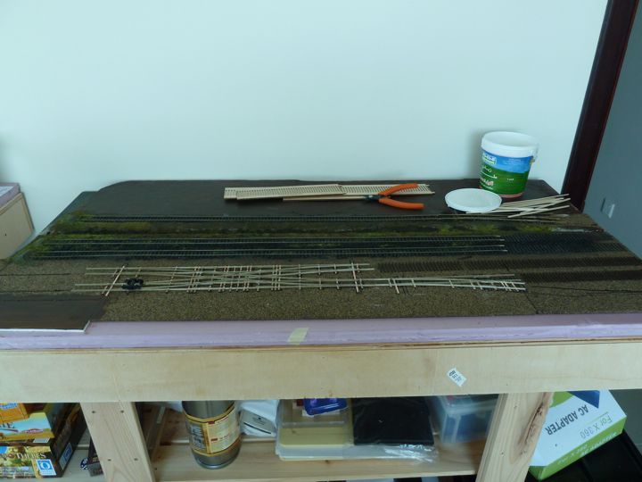
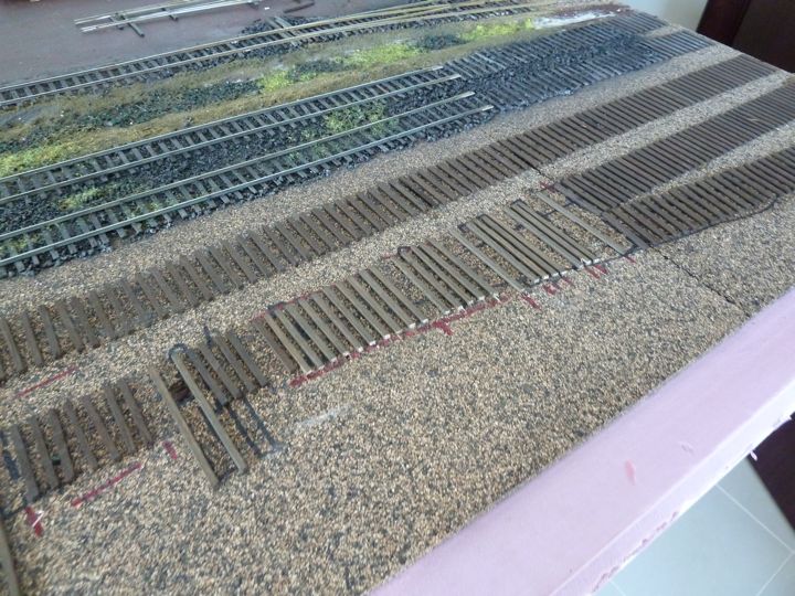
Back to work on the module, it's time to put down the yard tracks. First up was putting the paper template back down, and punching through it to set the guide lines, than connecting the dots with a sharpie.
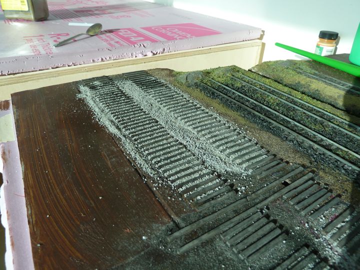
And than laying ties....as well as some limestone sand in ditch (just playing with it for now).
The weathered ties come out very fresh from Micro-Engineering, as I've mentioned they should be named stained, not weathered ties. I do want to lighten them up, sans spray paint.
Here are the fresh ties, glued down.
And with a brush applied light coat of gray
And with a coat of Joe's Weathering Powders (gray)
And after spraying water, and that dried.
Then came ballast, and white glue
And after the glue dried.
You can also see I've started to "scenic" the ditch a bit; mostly I was just messing around, and put the foam down as a base for what will come later. I figured I had the glue out anyway.....
I actually like hand laying, it's not that much work, actually, and it does provide a nice sense of satisfaction when you're done. I find it is a very enjoyable part of the hobby, and I'd recommend that folks give it a whirl.
With the new MOW offices in Montpelier providing some incentive, it was time to get back to work.
The crews put rail down on the two yard tracks that were ballasted.
And after some wiring work, every thing tested out well.
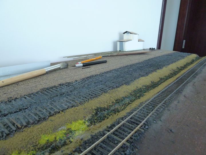
Some additional ballast, ground turf, and some light grass was added to fill in some holes.
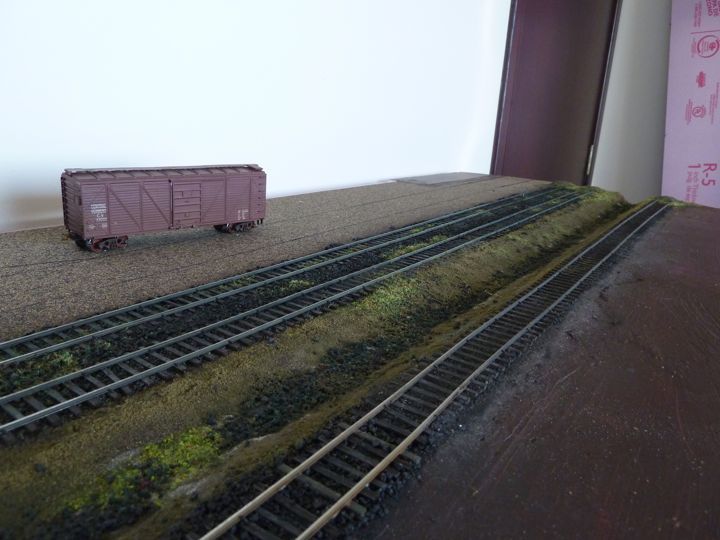
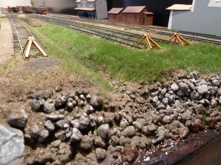
And mounds of extra ballast were put at the ends to keep cars out of the river. I have bumpers to add here as well.

I didn't put in too much effort into last night, but I did get the bullfrog completely installed, including the controlling rod
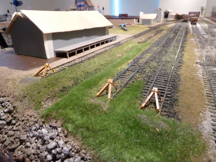
And assembled some track stops (this is a Peco kit).
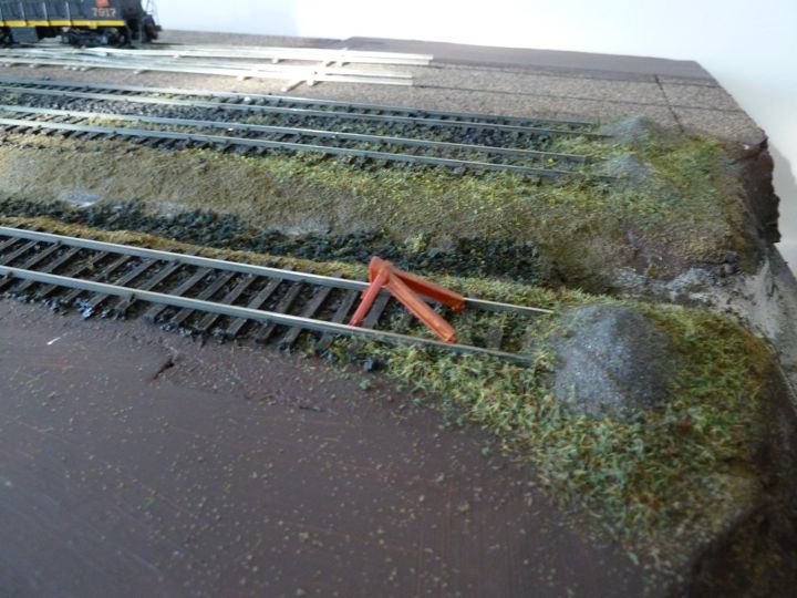
I need to paint these up prior to mounting; I'm looking at a worn yellow effect. Once that's glued in, than the static grass can go down, at least in this area.
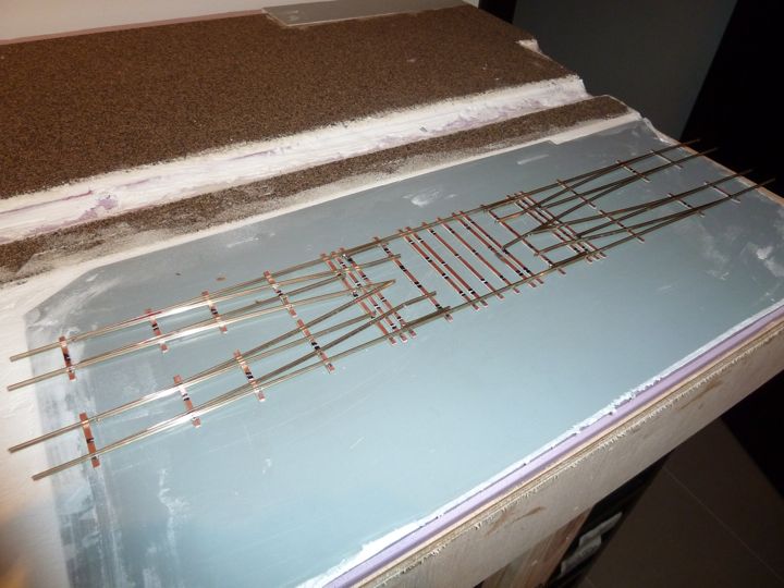
One advantage of the module style construction is being able to flip it around for axis. Here is the first one flipped so I can work on the rear tracks
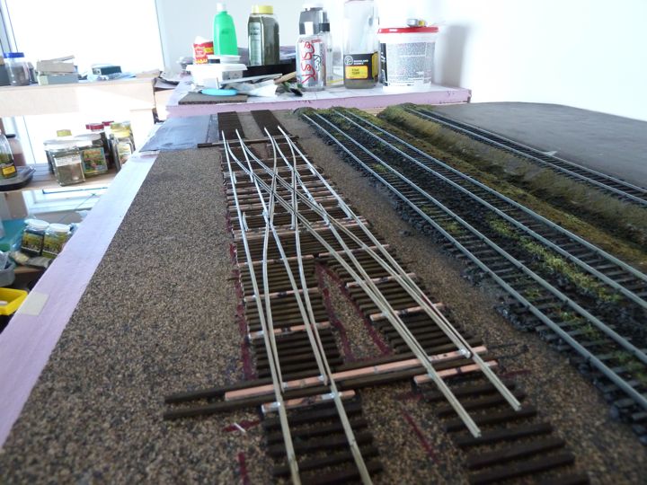
In case you can't tell, I've gotten the last turnout for this section done, a code 83 right handed no. 6.
With that done, I was able to put down the rest of the ties for this first module.
Including filling in around the Fast Tracks Turnout.
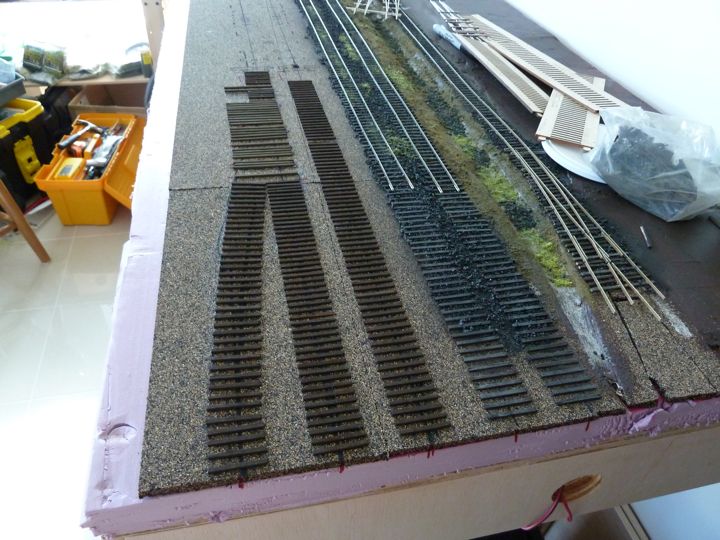
And, the double crossover. Phew.
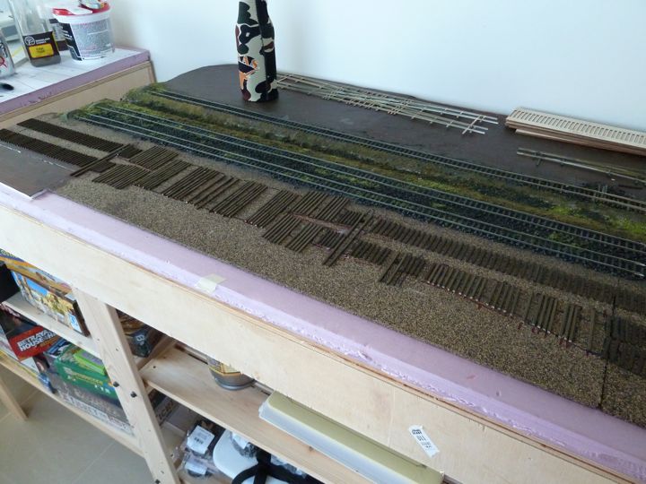
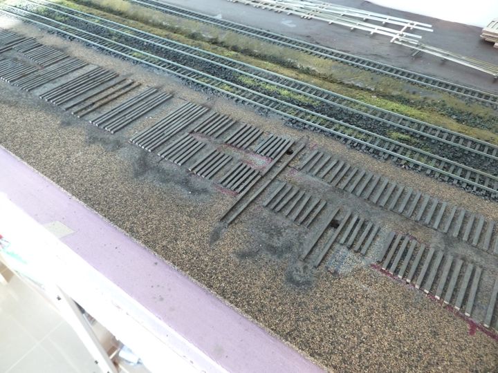
After they dry, I like to trim the tie lengths to fit, as I was able to do on the turnout.
I don't feel like I got a lot done, but I know these stages are deceiving — getting the ties down is a huge step in the track laying process, and every little bit spent working on the layout is not only that much less to later, but enjoyable to boot!
Once dry, I was able to trim the ties to fit the width on the crossover as well.
There is a lot of lumber in this thing!
There was a great discussion on creative crossover/slip controls that got me thinking about my own. It was my intention to run four separate Bullfrogs, one to control each point, but I realized that was crazy in many ways.
I ordered the Tam Valley Mono Frog Juicer from Fast Tracks to handle the electronics, and decided to use a single throw bar across each pair of of points run by a single Bullfrog. This give me a total of four positions, and should work fine as either traffic on this line will either be straight across or using the crossover (I don't expect any continuous running right now for this crossover, so I think it will be fine).
That crossover was a much more difficult project than I expected. It also sucked up a lot more resources in the way of ties and rail than I had estimated, I'll have to deal with that later.
I got the ties weathered, in the same scheme I've been using (over brush gray paint, gray weathering powders).
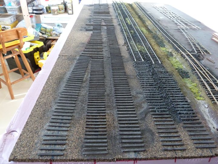
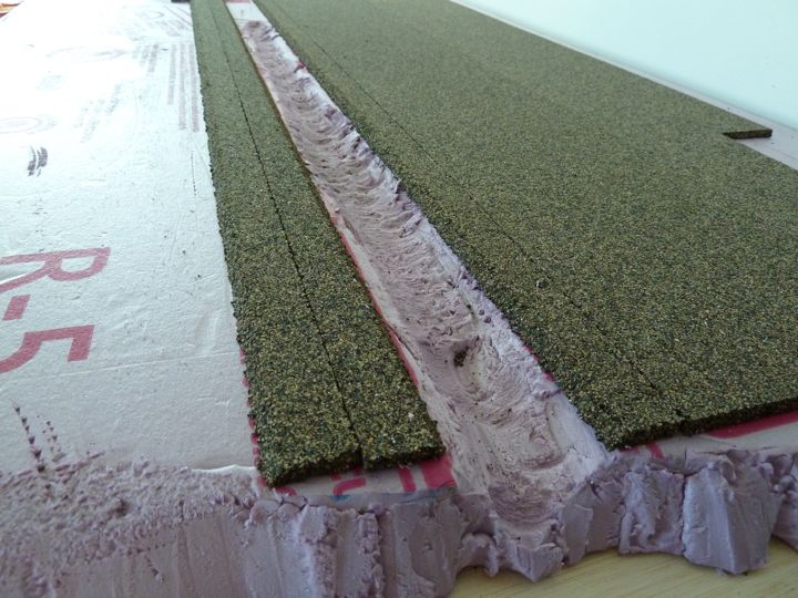
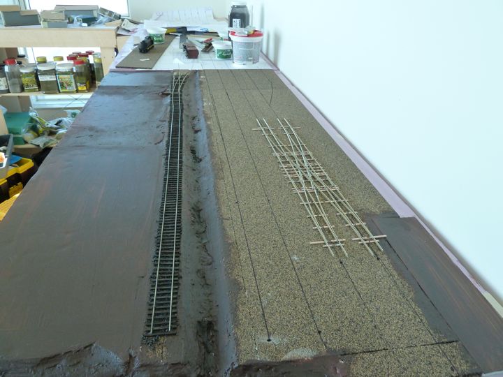
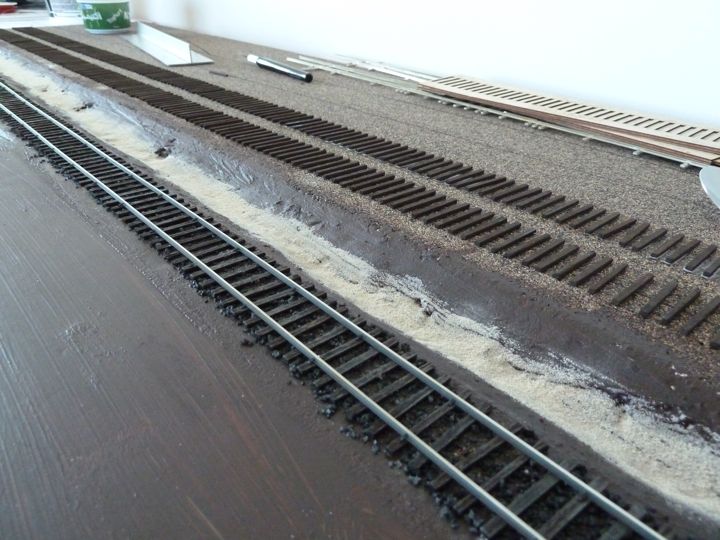
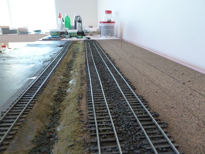
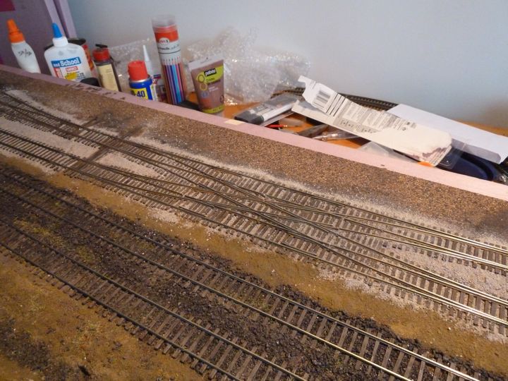
I was able to get some ballast down though, as there was enough left to do for now. As this is the mainline, it meant I needed to create my ballast mix.
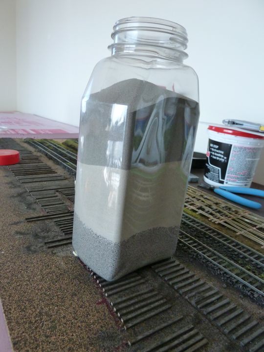
From the bottom up - Woodland Scenics medium gray ballast, Highball N scale light gray, Highball N scale dark gray. Mix well.
Once dry...
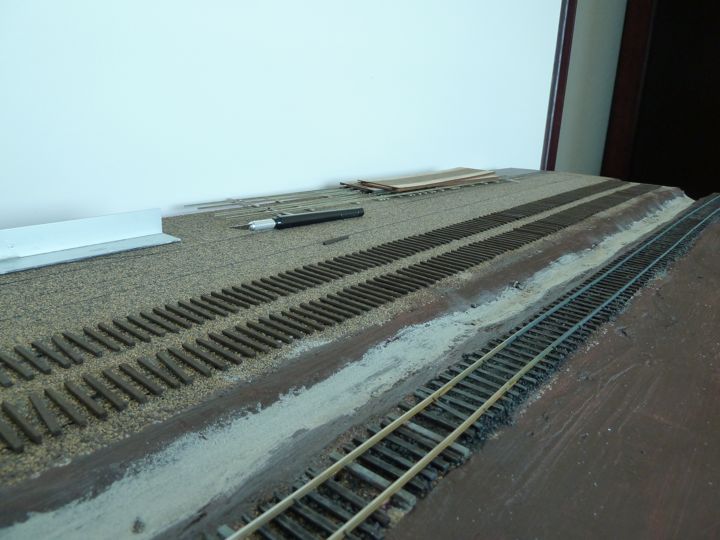
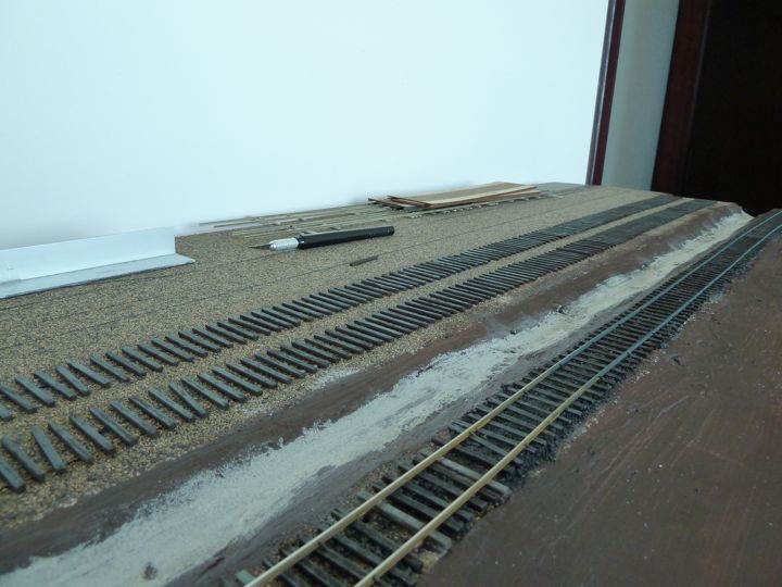
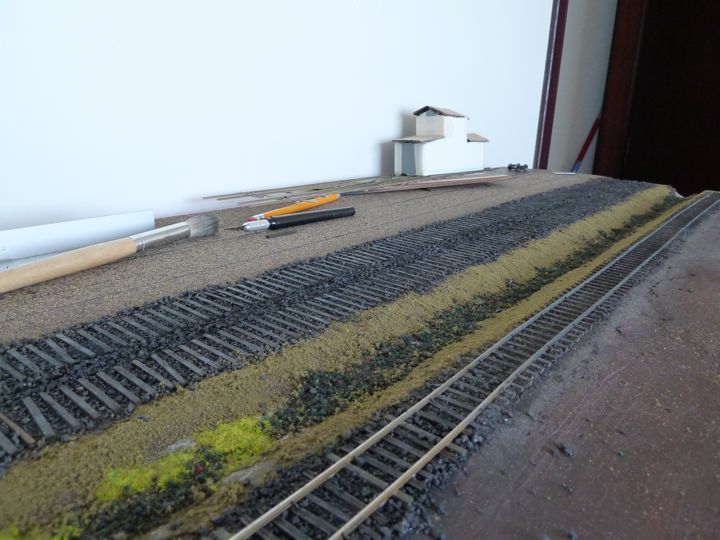
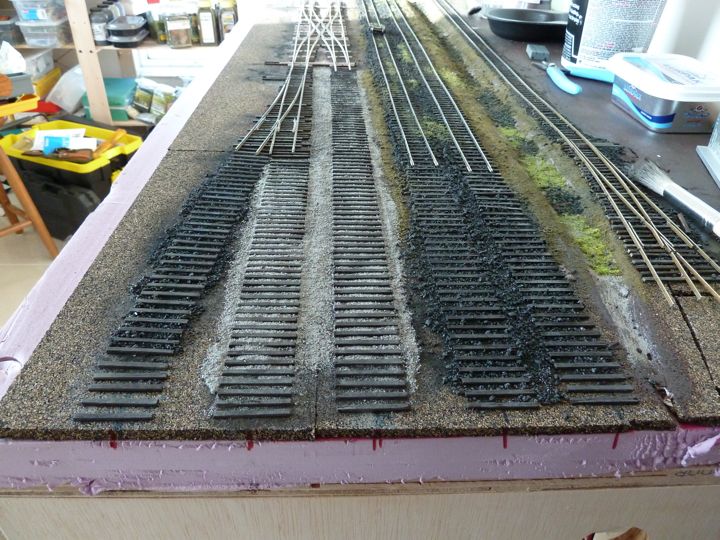
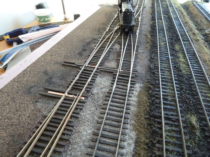
I like this next shot as it shows the tie spacing well. I use the Fast Tracks tie jigs, and left to right is the siding, main line, branch line, siding, siding.
I was awaiting a package from Fast Tracks that finally arrived. In it was the Jeweler's razor saw I needed to gap the double crossover, and perhaps more importantly, a new rail nipper (after I messed up my last one).
I got the whole thing gapped and isolated, and before soldering in feeders, went ahead and painted up the crossover. I'm using the Floquil pen set for this.
First step for me has been to do the pc ties with a black sharpie first as a base coat.
Then go over them with the Tie Brown pen.
The rails come next, with a coat of rail brown
Then finally a coat of rust on the rails (and a retouch of tie brown where needed).
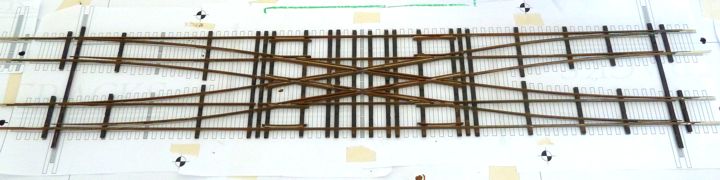
Once dry, it's ready to go. In my case, that means adding feeders, cleaning off the rail heads, and installing!
The crossover was mounted, feeder wires in place and connected, and the single frog juicer in place. Even put down some rail coming in and out of it!
Best part is it almost works perfectly - just need some fine tuning.
So there is one "dead" leg of the crossover. Not a short, but instead a path that simply has no power. I decided it needed another feeder, and so one went in here (I wasn't happy with doing it from above, but there you are. One eyesore isn't too bad, after all).
Pre soldering......
And I tried connecting that feeder to the frog juicer along with the other one - short. I tried connecting the new feeder to the red track feeder - the dead run was now functional, but the center paths created shorts.
I'm now of the mindset that this needs it's own, dedicated juicer to function properly.
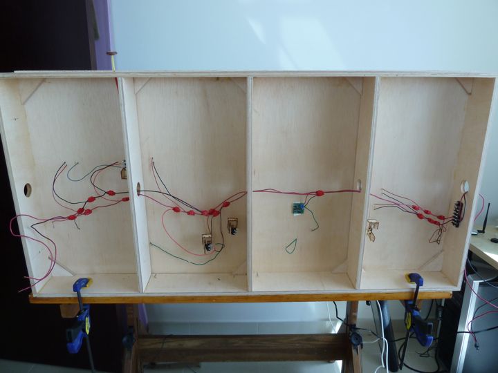
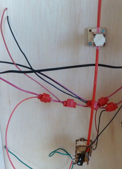
So just to be clear, I've created the picture below. The yellow path is the dead leg. The red and black balls indicate normal power feeders from the bus, and the green goes to the frog juicer.
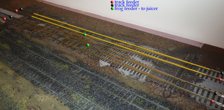
The good news for me is that of all the paths to be dead, this isn't a bad one - after all, the layout terminates just to the right of the crossover, and it's not that necessary even for operations - but I would like it working, of course.
I had time to turn this module up on it's side, and finish (or attempt to) most of the underneath work. I built some Bullfrogs, installed them, and wired up the frogs to the bus.
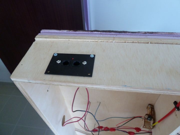
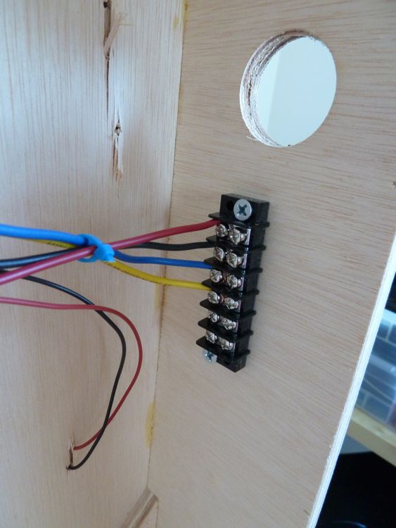
I also took the time to install the face plate for the NCE Powercab
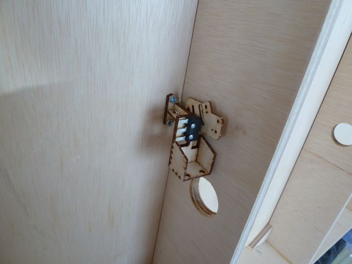
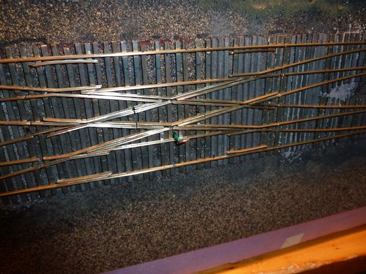
After that, I ran the control rods. Despite this turnout's appearance, it didn't work - I can't get the points to move. I messed with a lot of things, including re-drilling the hole through the plywood, and ultimately ended up smashing the throwbar (now replaced) with the drill bit, etc etc. In the end, I pulled the whole thing, and will start anew with this one, I think the issue is clearance, and will make a new bullfrog in a reversed profile (I should be able to rescue all of the parts to this one).
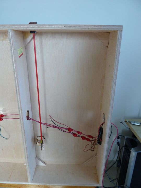
The others, such as this one controlling two points on one end of the double crossover, work flawlessly.
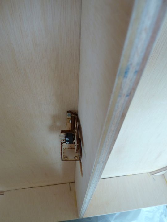
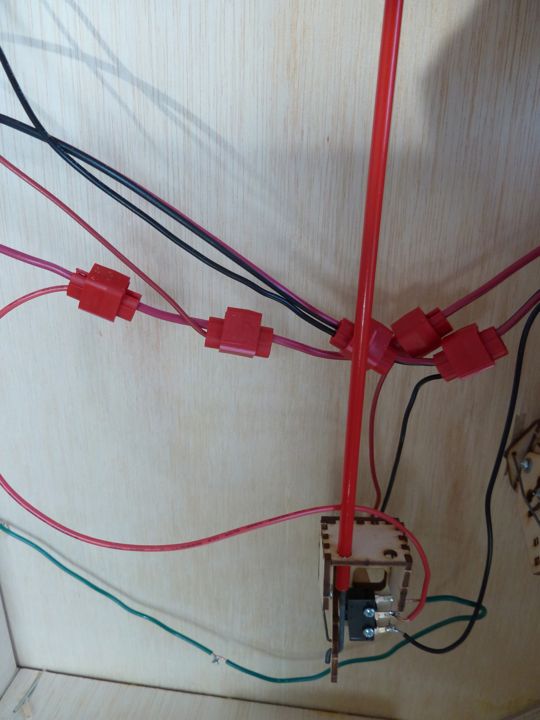
My next efforts were spent on replacing the control rod and bullfrog. Lets just say that this new setup works great! Well worth the time to redo, and redo correctly. I also added a control rod extender, as this was right at the end of 18", and may have had something to do with the earlier problem.
A shot from above, with the new throw bar.
So far, its testing well, only the tender on the 0-8-0 is causing problems, and I think that's due to light weight.
A shot from the front. I spaced the pulls vertically depending on how close they were to the front, now I'm not sure I'll continue that idea across the rest of the layout.
Well with the underbelly mostly squared away, I can work on the top. First up was ballasting the entire crossover, and the single switch. This is already dried, and yes, the points still move...
I finally received the other needed Frog juicer, and the double crossover is wired up, and working. The turnouts are all switched, and work well.
See for yourself!
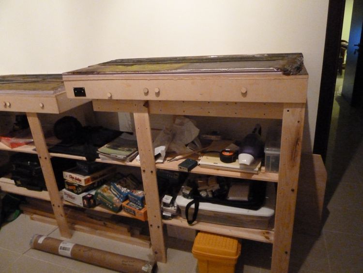
I encountered a huge problem when I added the second module.
One of the benchwork legs lie directly in the path of not one, but two turnout controls.
I considered:
- moving the turnout controls
- cutting into the benchwork leg
- sliding the modules up and down to see if I could get them fit (tried, and failed)
- raising the modules to sit flush.
I'm leaning strongly towards the latter. I was afraid to move the turnout controls, as I may come across the same thing again further down the road, but I prefer the height of it being a bit lower. There is a big advantage to having the modules sit on top, as than all of the components sit within the module itself without obstruction.
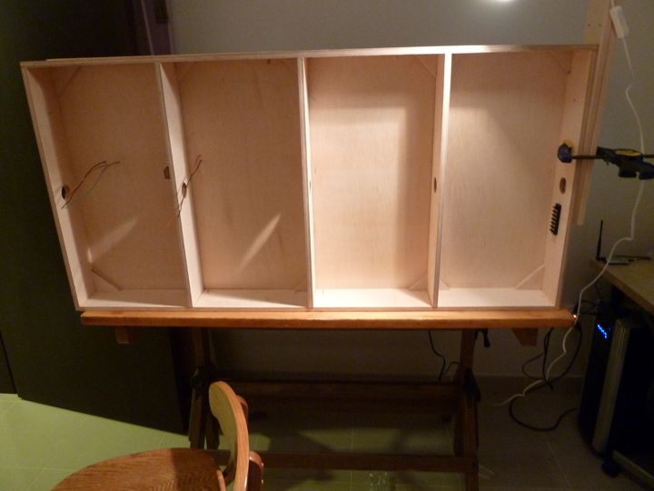
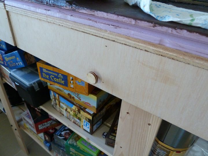
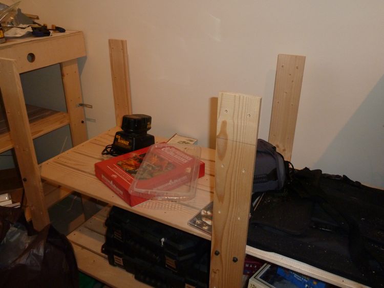
As a test, I grabbed two extra posts, and screwed them in place flush with the tops of the other posts.
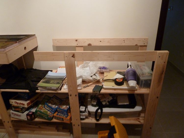
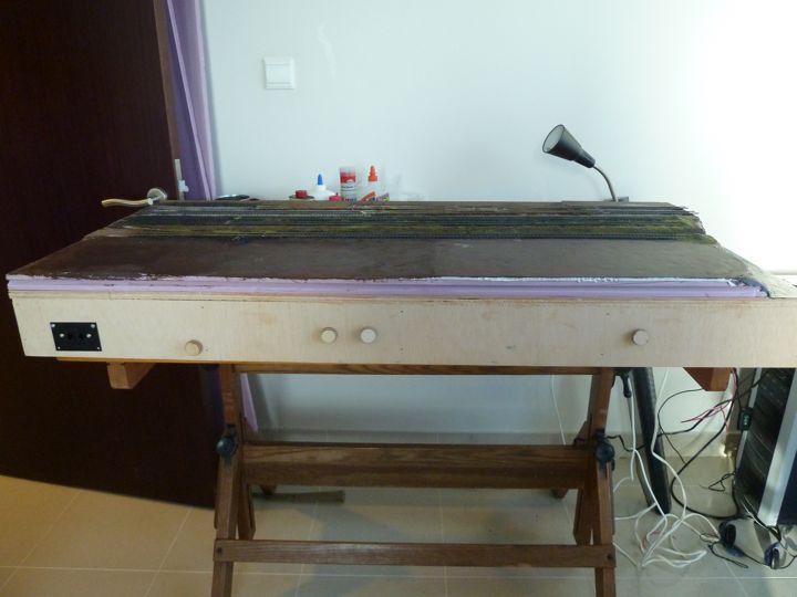
and set the first module in place.
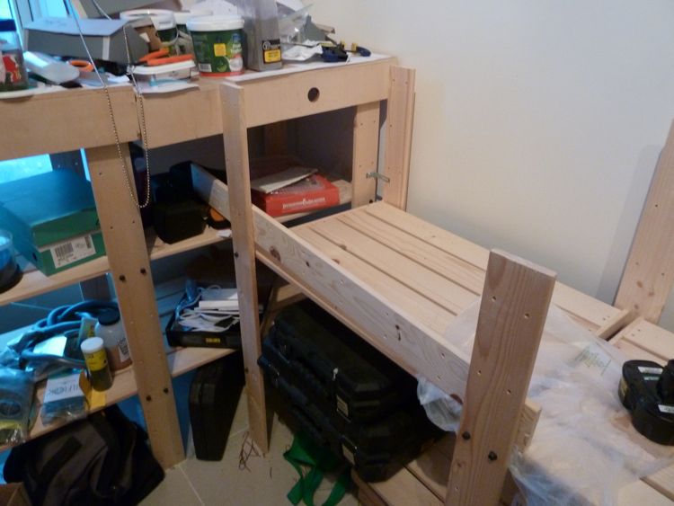
you can see how much higher it sits (almost exactly the thickness of a module)
I played for a few minutes with it at that height, and while it does raise it up a bit higher than I wanted, it does move the turnout controls out of the "belly bumping" range, and seems still easy enough to reach the Sergent couplers between cars.
I wasn't sure if this is the way to go - moving the controls might be the right move, as I can mark where the legs fit in the future and avoid them. Or simply raise the whole thing up. I'm not eager on the idea of cutting down the posts, as I was concerned about getting straight cuts with the tools I have on hand.
As a test, I have put a car at the back siding, and was able to reach it. But for reasons that I cannot explain, I didn't find the new height comfortable. And in the end, that was enough for me to not go this route.
I thought about a stool, but if I can eliminate another "unnecessary item" in the room, than that's an advantage. I also tried to think about other people than myself — with any luck, I won't be a lone operator down the road, if I can coerce some of my local modelers to join in. That being the case, than we may be looking at multiple stools in an already small room, which seems a bad idea.
It was suggested to cut off that single post, and run a horizontal support along the front of that one module. I decided to try this as if it doesn't work, I can replace the post easy enough and be right where we started. To avoid in the future, I will need to mark post locations, but now that it's on my radar, hopefully this won't replicate farther down the project.
So...the fix.
First up was marking the leg for the cut.
Then, of course, the cut.
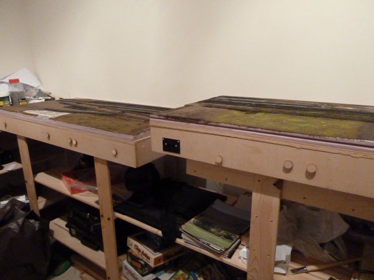
With it trimmed, I put down down an extra leg, and realized that this may be a really great idea, as it can extend under and support the corner module (it sags on that side).
A couple of clamps, a right hand clamping square, and a through lag bolt later...
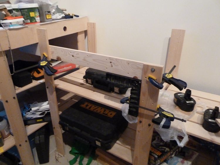
The fix is in place, and the module(s) down. This, is going to work.
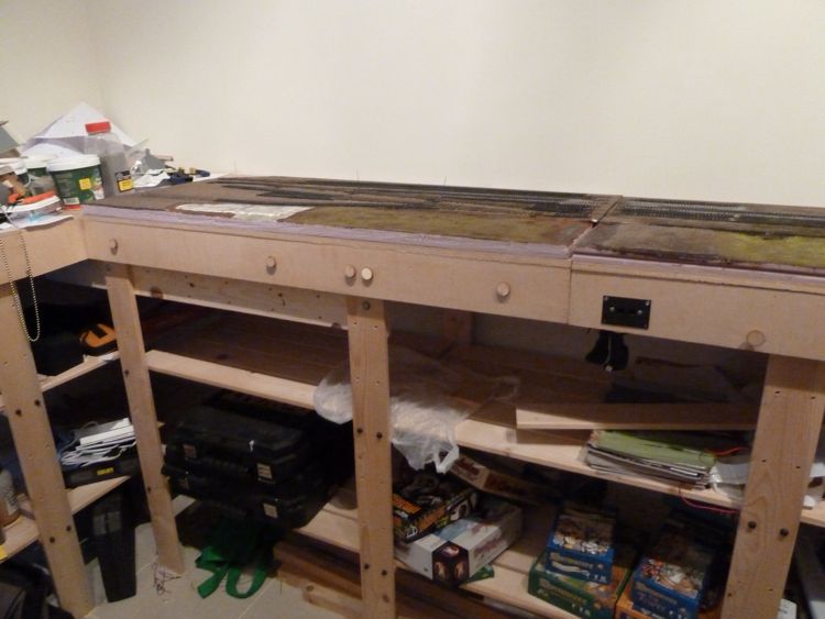
I'm very happy this fix works (thanks for the suggestions) as the greater height wasn't appealing. The top of the benchwork is at 44", raising it would have been another 5 to what felt like an uncomfortable 49". Now I need to be wise to the fact that as I add modules, I need to dodge those posts.
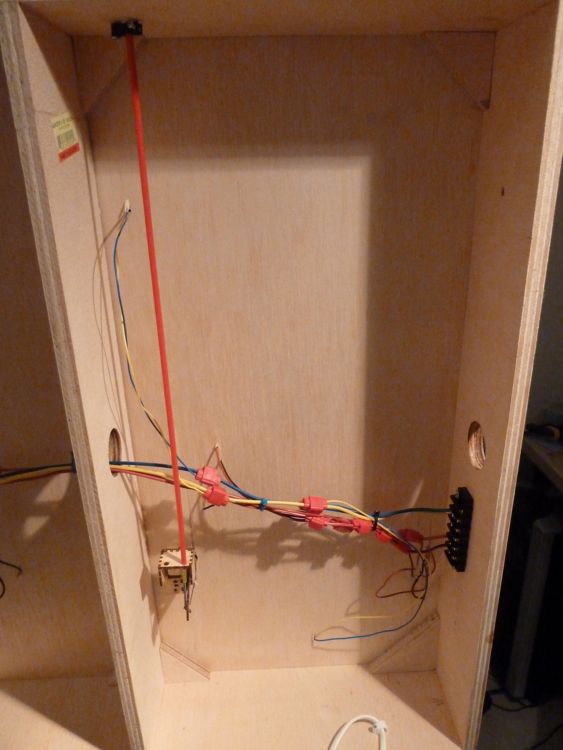
I decided to add a second electrical bus before I got too far with construction, shown here with the yellow and blue wires.
Why? well I placed an order from Micro Mark, and as part of it I chose a package of their Mini Connector Kit. I thought while I have this upside down, I'll go ahead and put in connections for my buildings in case I want to add lights later.
With that in mind, and as my order hasn't arrived yet, I pre-drilled some holes where the buildings are going to sit.
I drilled holes, and cut a section away so the micro plug (female end) sits flush inside the hole. This one is for the freight house.
underneath, I have color coded these wires in yellow and blue - you can see the one here going up the left hand side of this section
Scenery
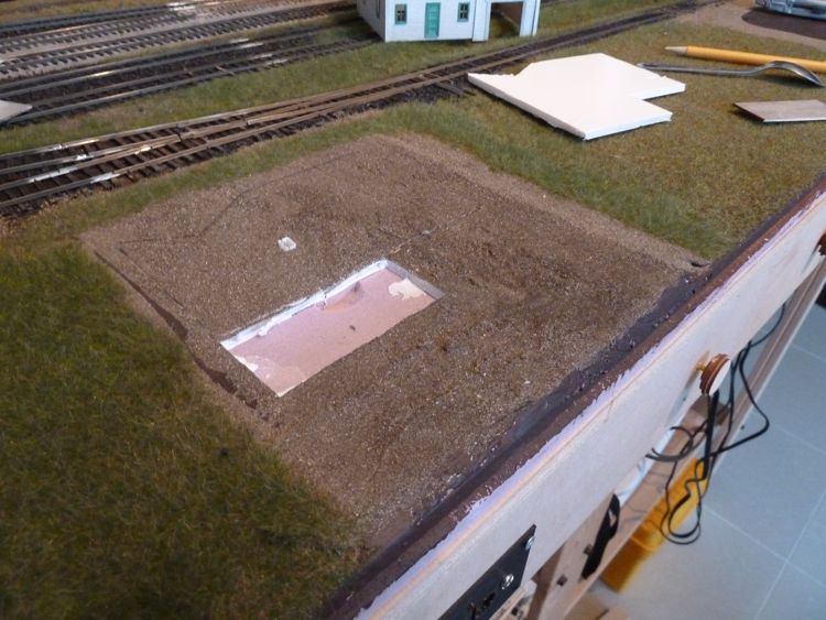
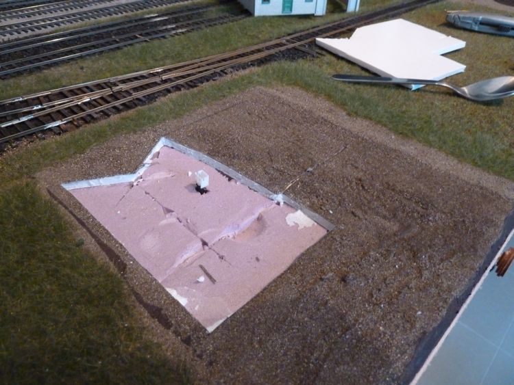
I was unhappy with the bottom of the water feature on this module. I've read from many sources, but most recently from David Popp at MR, that you can't just paint plywood; the grain shows through. Yup, they were right, and a coat of spackle went down to remove that problem.
Once the black on the river area dried, i touched up the edge with more brown.
I also laid down the "base coat" in this area that I intend on being mostly grassy, I like there to be something underneath static grass.
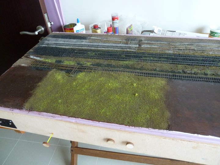
I use Woodland Scenics fine turf "earth" under a dusting of summer lawn mix from Scenic Express for this base coat.
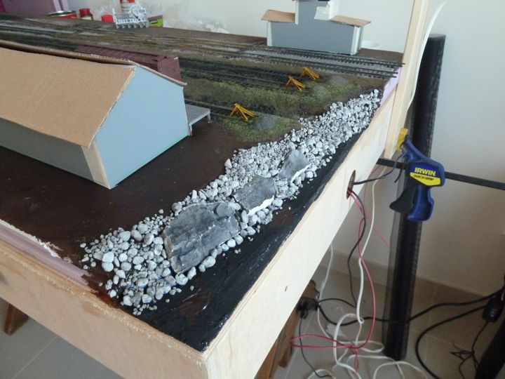
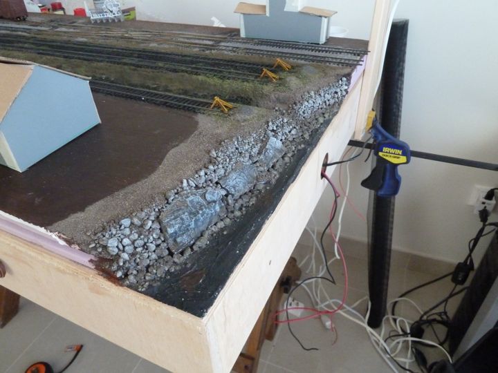
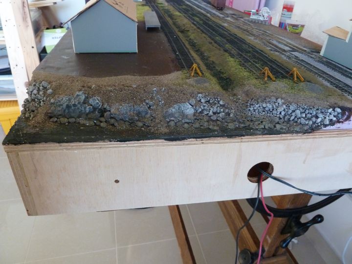
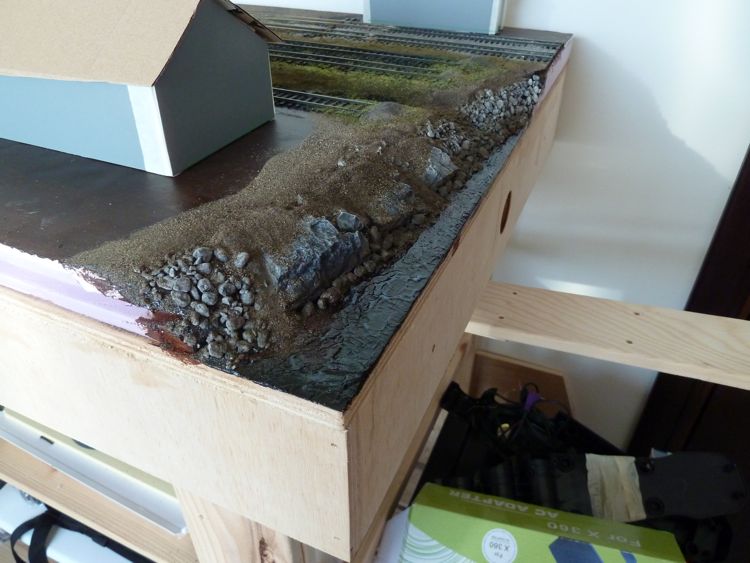
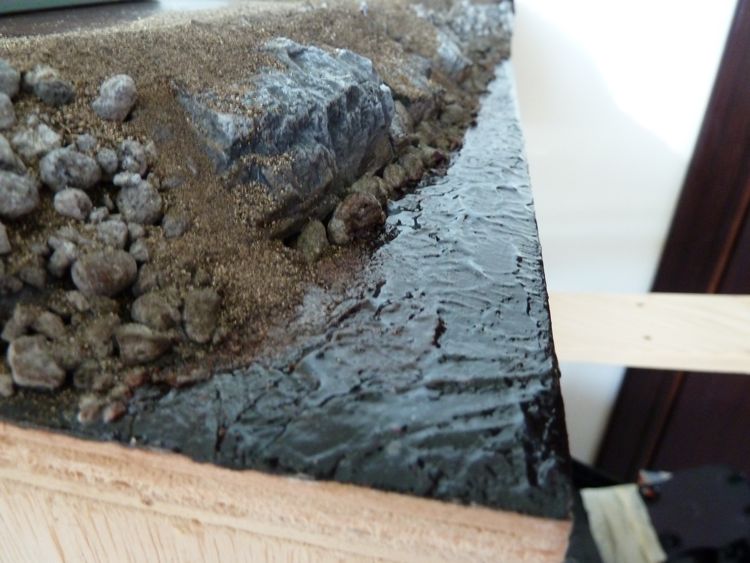
I got the river bank roughed in with stone. I want this to look like a decently maintained area (as close to the tracks and buildings as it is, hence the smaller dumped stone (common in a lot of NE areas). I need to blend/stain/paint them, than produce some overgrowth on it once the water is in place.
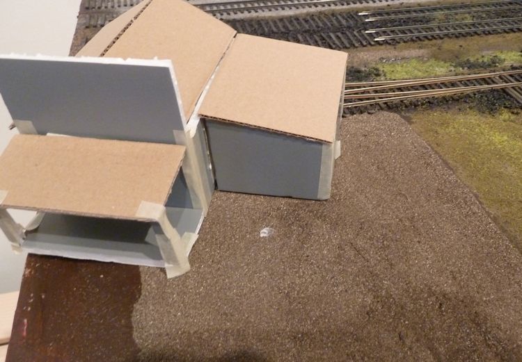
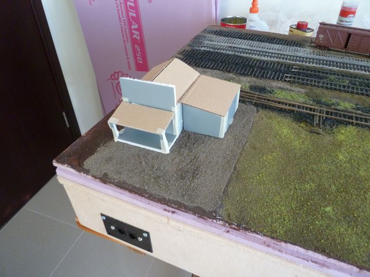
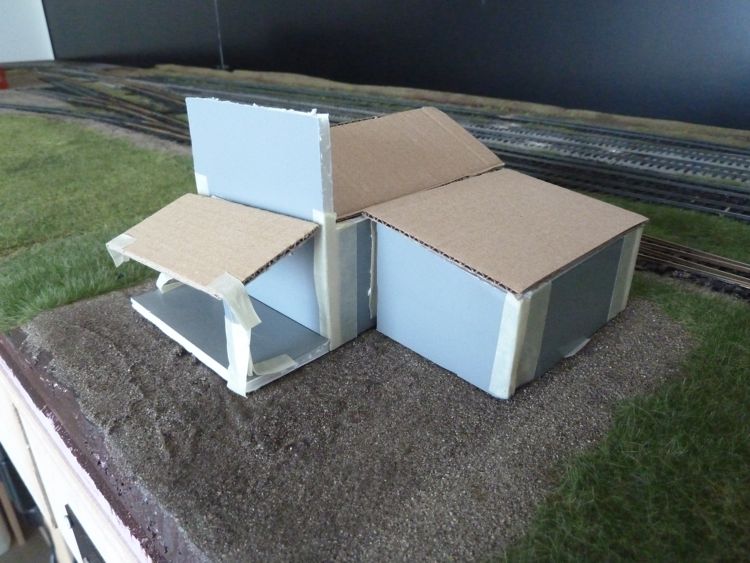
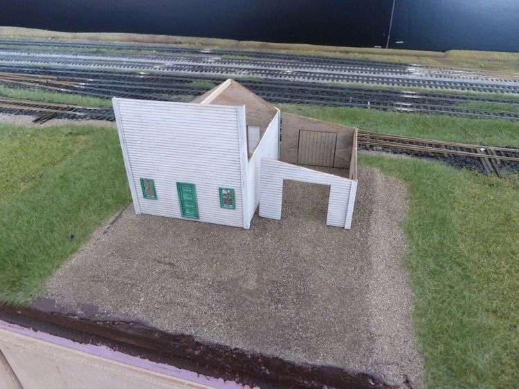
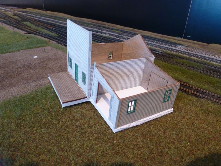
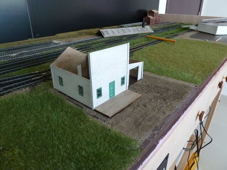
If I haven't mentioned it enough, I love having the building mockups. They really help in verifying that the look is going to be what it's going to be, and are simply more fun. Well worth the time!
The entire bank got a wash of the Woodland Scenics slate gray to blend in the castings with the talus.
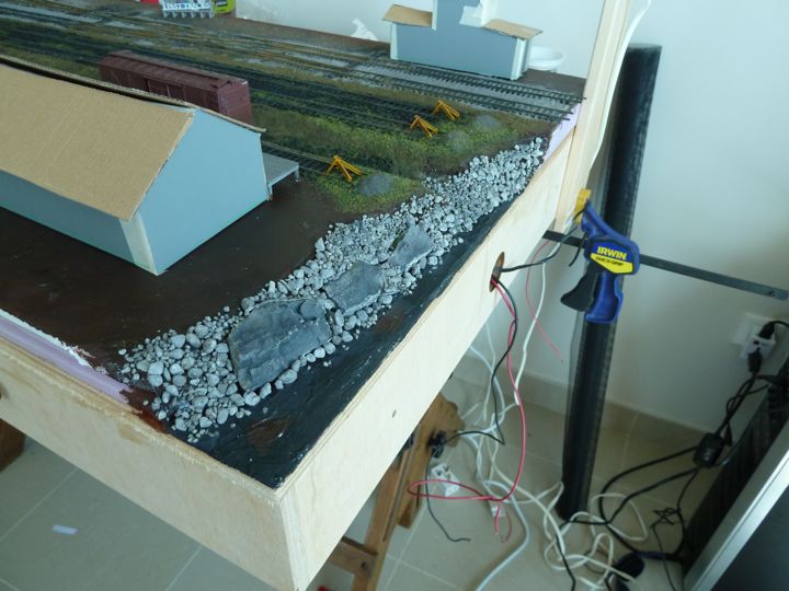
Then a light dry brush of light gray primer (Poly Scale), and than the bottom edge received a heavier dry brushing of roof brown to indicate the water line.
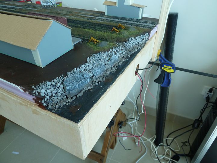
Finally, a layer of algae growth using the Woodland Scenics green terrain wash.
Now to figure out what to do for water, based on my locally available materials.
It should be noted that the castings were old ones I've repurposed (read broken by hand and just stuck in). I won't claim they were created for this space; the look I'm hoping to achieve is that this bank has been reinforced with some fill, but there is some natural ledge underneath.
The river bank here isn't supposed to be a major feature, but instead merely indicate why the yard tracks end. It was Byron Henderson's idea, and I think a good one.
I know I can get urethane, but I'm may just try white glue for a base coat, and artists gloss medium (which I think I can get here) for the top. I have a much bigger river section coming up which is a major feature, so this will become a test area (live fire!) of sorts.
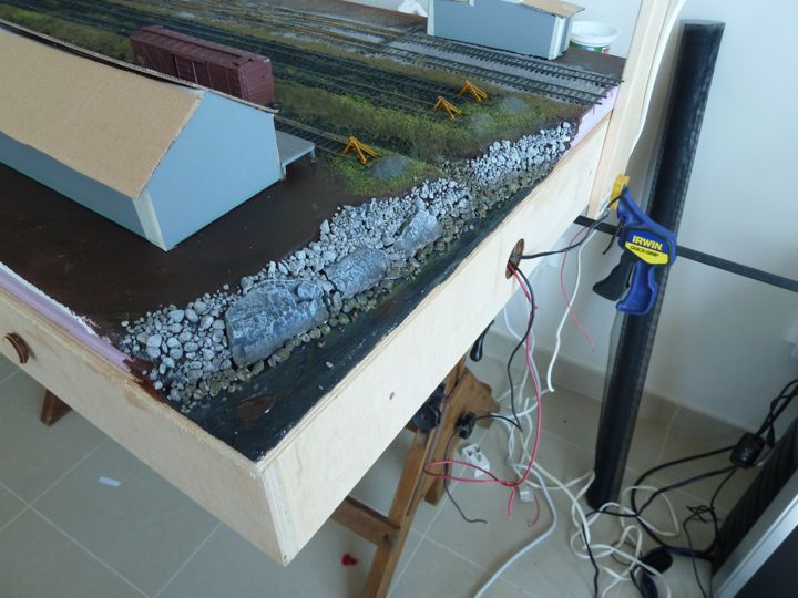
Back to the bank, it received a dusting of sifted, microwaved local dirt (which has an unsurprising amount of sand content!).
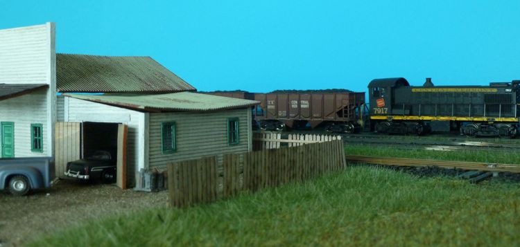
As I had the dirt out, I went ahead and did the Vern's repair area. This will need to be blended a bit better with paints I think.
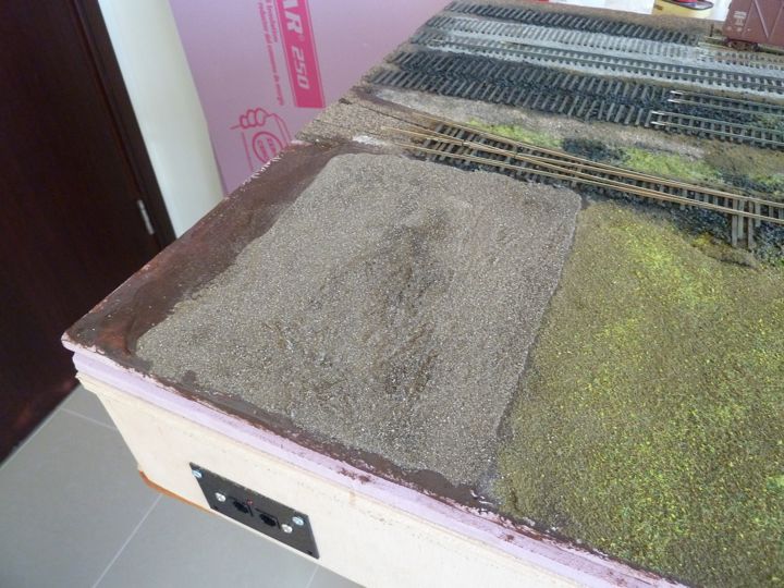
With the dummy building.
I attempted last night digging out the rock castings I put in. No way — I have apparently used enough glue and water on this whole bank that it was as solid as, well, a rock. Not wanting to create major damage (I was hoping I could just pop them out), I decided instead to fill in some above, and around with some more dirt.
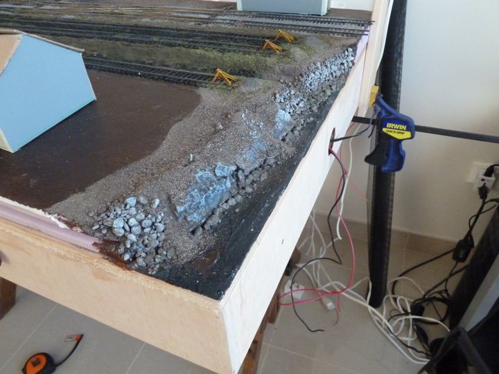
Still not 100% what I was hoping for, but it does look better - and I think once there is some growth along the top of the bank and in a few spots along it, it will look ok.
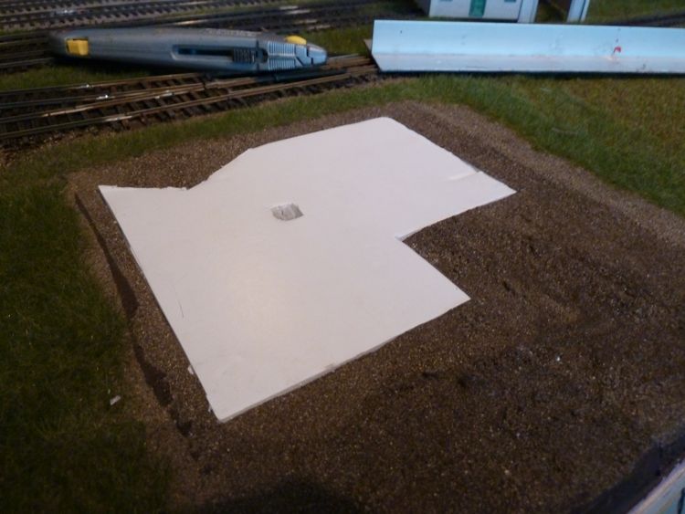
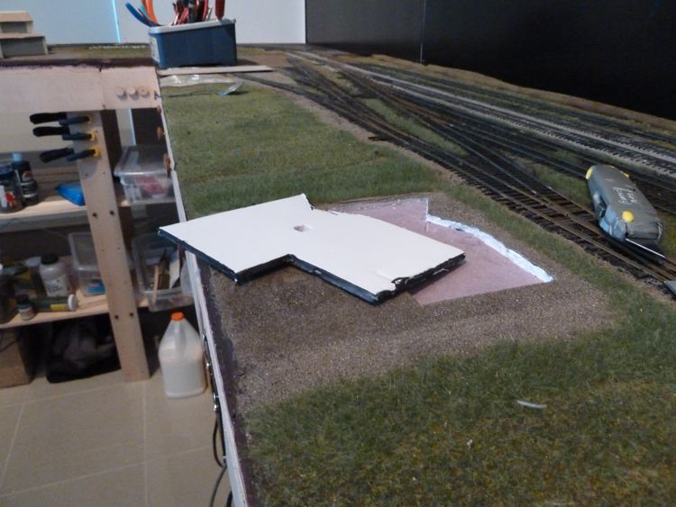
One thing folks are not aware of though is that on the ends of the layout, there is a plywood cap (meant mostly to contain errant railcars). I thought it was about time to try one out here, to see how much of this feature will really be visible with it in place.
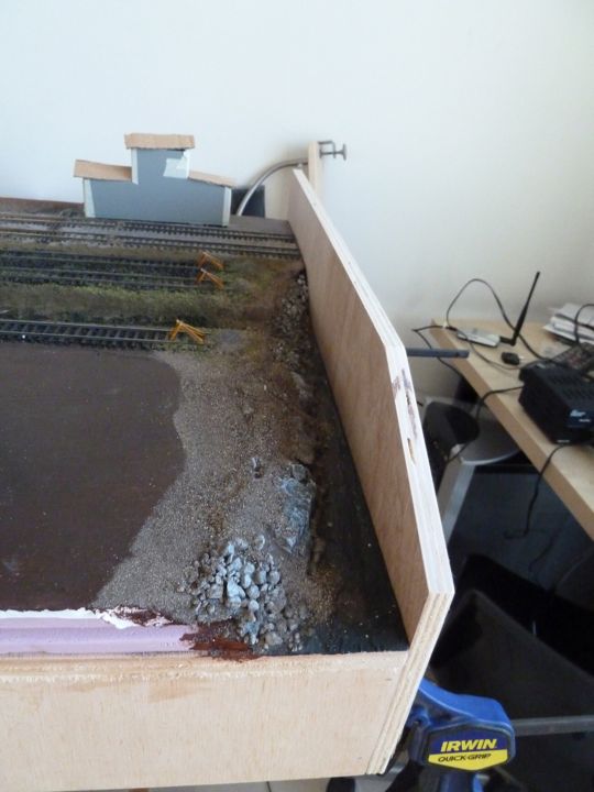
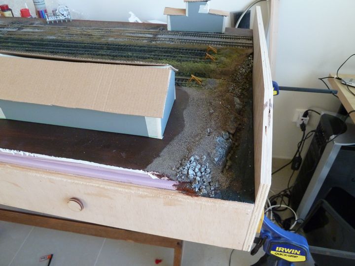
You can see that with the cap in place, the bank and it's corresponding imperfections are a lot less noticeable than before. I'm thinking this should probably work fine....
I was able to get some artist's gloss medium at a local shop. I applied it with a brush and then let sit for two days ago, and here are the results
close up
I think I'm going to put a wash of brown color down, and than another coat of the artists gloss.
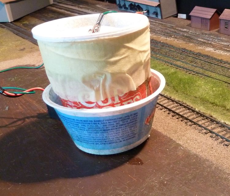
My home made "grassinator" didn't survive the move overseas; I sadly didn't find this out until last night. Some quick work with some glue and a couple of used plastic food containers, and I was back in business.
Don't laugh (well, at least too hard), it works.
Once things had dried, I removed the excess I could save easily, and vacuumed up the rest. The results?
It's a little too uniform for what I was thinking, but I have some longer brown static grass I can mix in.
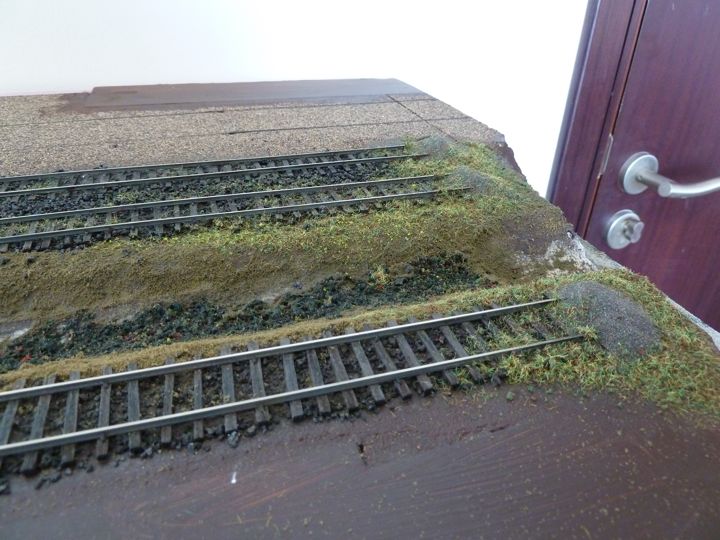
These show why I go though the "underlayment" step with the earth flock, and I think the ditch is starting to look a lot more like what I had envisioned. That's always a good thing!
I'm pleased though, the static grass application method really does make all the difference in the world.
I do think it's a bit too green,
As a result, I'm making a custom mix of static grass; 6mm yellow, 6mm green, and 4mm green (the first section was all 4mm green, hence the uniform look). The rest of the ditch and the area behind the building to the right are the new mix; what I'm angling for is a variety of heights, texture, and color. I'm hoping that when it's all down, it will look varied enough to look more realistic.
I'm even planning on a mowed section! (I have 2mm grass for that!)
Overall I'm pleased with the grass so far, once I get some bushes and things like flowers in, I think it will really begin to pop.
Building —Tower 2
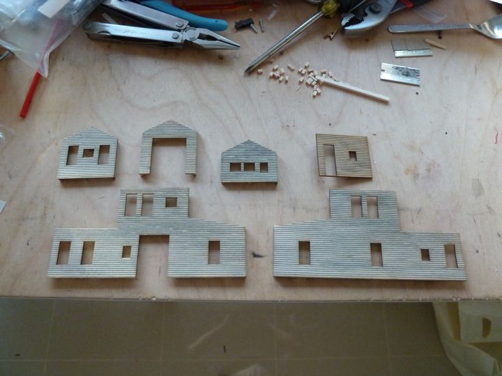
I've begun construction on the Tower Two kit from FOS Scale. Nothing to show yet, just completed the initial interior wall bracing, another long glue and wait process.
Following their instructions, the interior walls were braced with the supplied materials, and then "painted" with an india ink/isopropyl alcohol mixture.
Once dry....
I can now apply the surface paint.
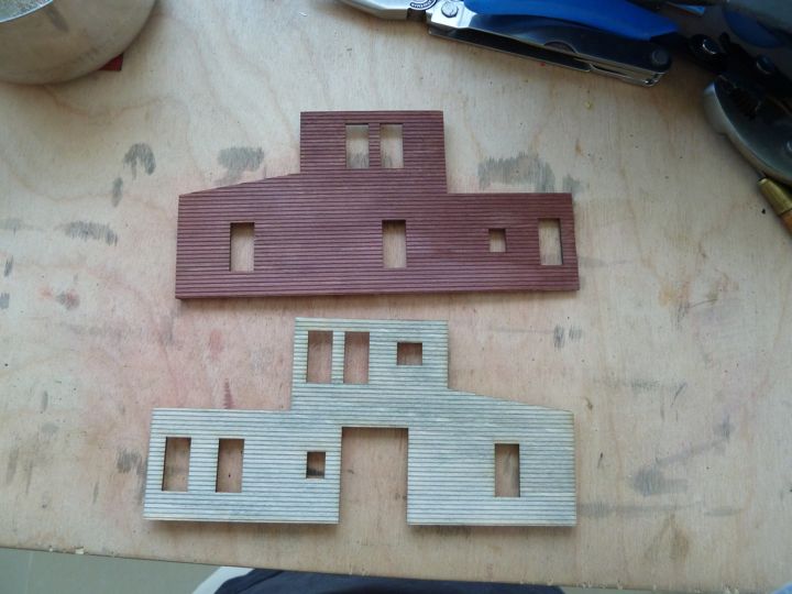
As a test, I tried a section of wall from another kit and a pastel chalk - I like the chalk, but the color is way to bright (the building to the left is more of the target I'm working towards).
I'm going to see if another ink wash will darken it up enough, but I may be headed in another direction - maybe even just painting this one, and saving that bright red for the Engine House.
With the walls "seasoned", I was able to put the base coat of paint (PolyScale DGRW red) on the exterior wall surfaces.
The windows were painted, and installed on two of the ground floor walls.
This color scheme is close to prototypical, based on some information kindly provided by Marty McGuirk in a forum thread on MRH. I'm going with just close here, as the building didn't exist on the CV anyway (I just like it).
Before I put in the glazing, I wanted to weather the structure a bit first - I was thinking from a maintenance standpoint, it's easier to clean windows than scrub walls....
After getting the paint on, windows and glazing in, and the sub-roofs on, here's how it is looking
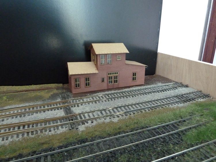
This model was painted with an india ink/alcohol wash, and than with Poly Scale DGRW Red and Depot buff for the window trim. The small windows are not in yet, as I am going to model them open.
I haven't done the edge trim yet either, the pieces provided by the manufacture seem too big to me, and I may replace with some other stock I have.
Next was a few hours adding roof rafters and roofing.
The kit didn't come with nice shingles or roofing, so I made my own rolled material from black paper. Once it's weathered up (once this drys, I should be ok.
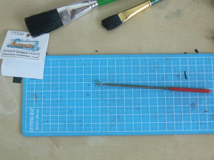
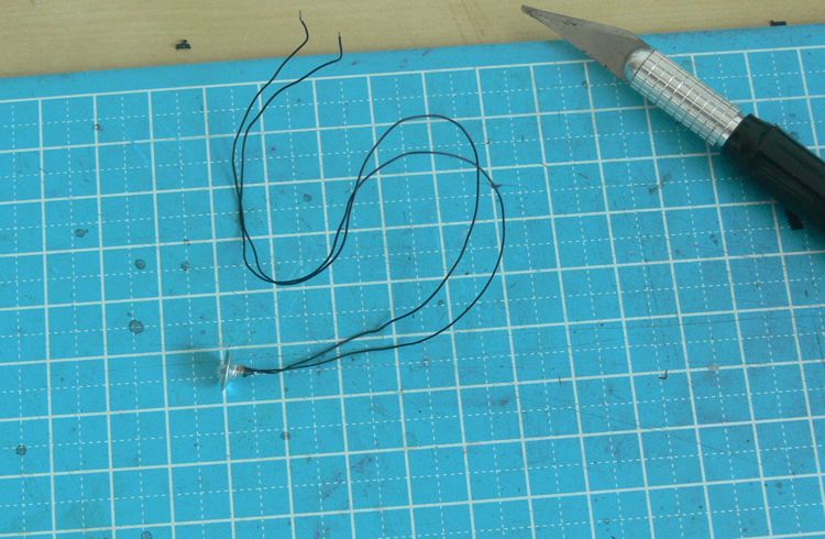
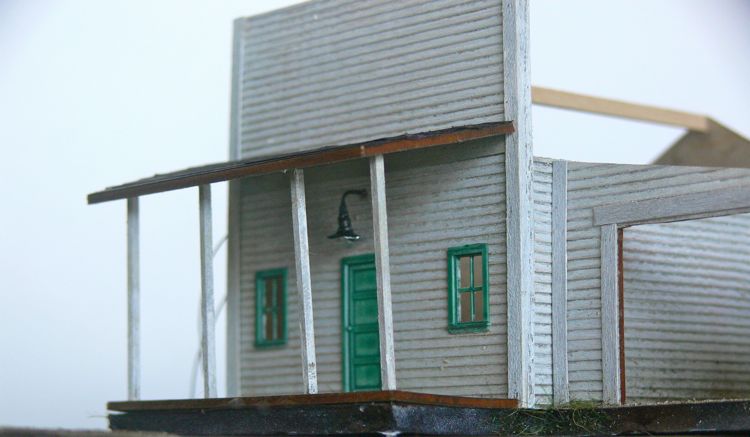
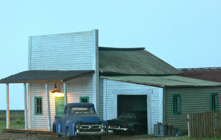
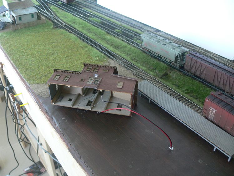
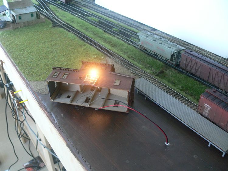
I also got the light mounted. Believe it or not, this is a working lamp!
The lamp is made of a grain of rice bulb, and an aluminum shade from Walthers. Clearly, I need to touch up the black out paint on the bulb, as it is shining through the top.
If you may remember, I mounted two pin connectors under each building, for easy removal. This is the first building to get a light. (it doesn't go here, but this pin was handier)
some weathering, a couple more windows, some details, and this should be basically good to go.
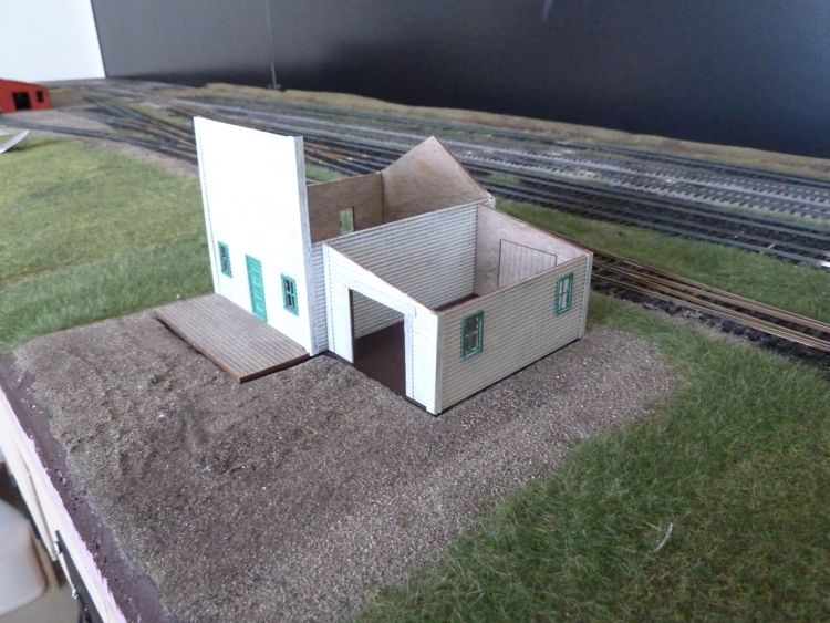
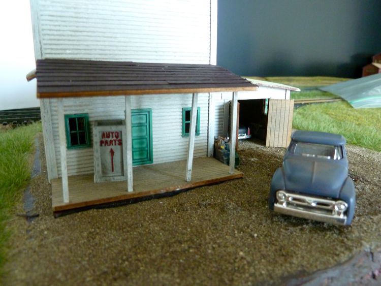
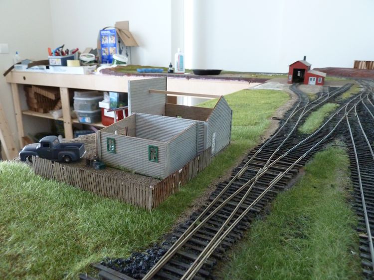
Building — Vern's Repair
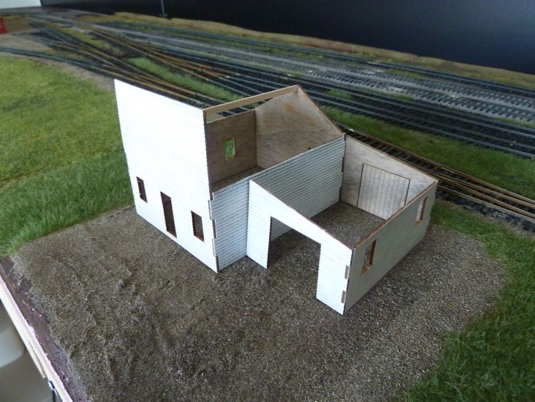
I began assembly of Vern's Repair from Creative Laser Design.
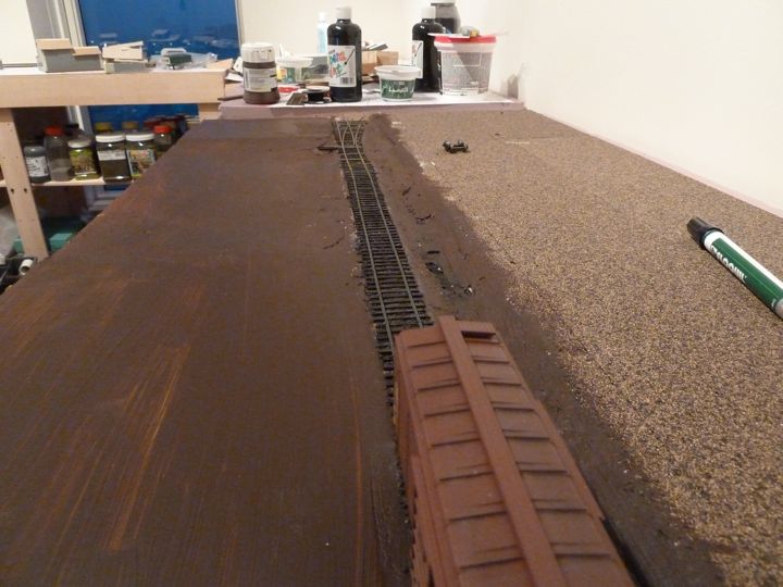
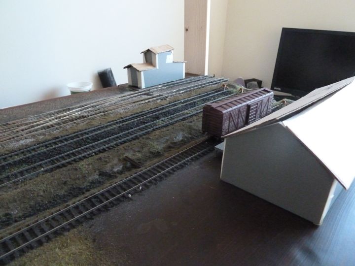
This model sits in the foreground in this location between the freight house and the engine shed
And is also starting to come along. This has been painted with the ink/alcohol wash, than heavily dry brushed with Polly Scale Aged White, and finally some surfaces were dry brushed again with a simple craft store white paint. I only say some surfaces, as I want the back (towards the tracks) to reflect a certain lack of maintenance.
I will have to modify this kit to some degree, it comes with a plywood base that I am not going to use (it's very thick, and also a fair amount wider and longer than the building) and I am not going to put on the rear porch.
Windows and trim are in on Vern's Repair.
The instructions and kit for Vern's Repair instruct you to mount the model on a piece of plywood. As I mentioned, the plywood is much wider than than structure, and a lot thicker than I would like for this application. Had I read the instructions prior to building the module, I could have compensated for both, but alas I did not.
The area where the building is going is actually foam board on top of the pink foam insulation, this was done to add some variety to the ground surface, and in other cases, raise the area up to the level of the road bed. The thought struck me - what I based the model instead on the same thickness foam core, and simply set the model "in" to the terrain?
I used to do this all the time with table top wargaming models. It's nice to see that some of those tricks are still pertinent.
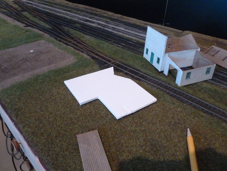
I marked out the building outline onto a section of foam core.
The clever observer will immediately note that the foam core base is not the full size of the structure, there is a large angled cut in the rear. This is to limit potential shifting of location while in place, as the shape will apply forces along many angles, not to mention....(note - the previous sentence was complete BS. I was simply to lazy and impatient to go buy an new sheet, this was a left over piece that pretty much fit. Odds are I'll regret it later on down the road).
I marked out the base on the module (the real dirt was murderous on my mechanical pencil!)
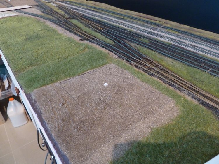
And started cutting. I worked it in sections, so that I could use one of the sections I was removing to pry up the other (this avoids damage to the areas I was keeping)
Almost there...
Done. Now it was time to test fit the building base.
pleased with the fit, I ran a marker around the edges of the foam core, just in case
I painted the top the same brown I've used all along.
With that dry, I glued on the front porch (and let dry)
Then the building itself
Once that had sat overnight and set up, it was time to check it out in place.
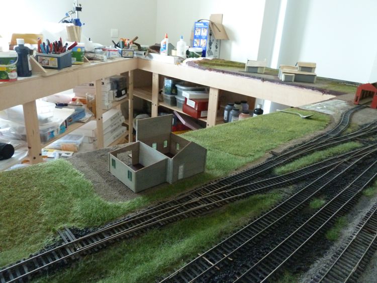
Ok, so this is working! I wish I had thought of this before I started any construction of any module, as this will make removal and storage of the buildings a lot easier. Hiding the edges in a semipermanent way shouldn't be that difficult.
I cannot do the engine house in this manner, nor the lumberyard buildings as they are direct on the pink foam (than again, maybe I can), but I can most certainly do the freight house, and all future modules.
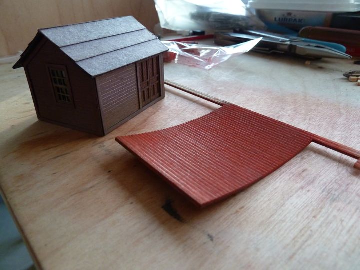
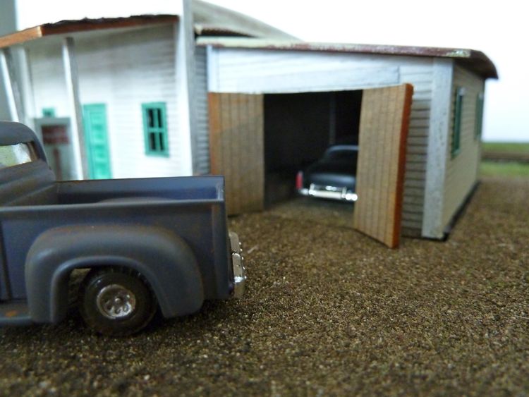
The porch roof is on, and the regular roof has been painted.
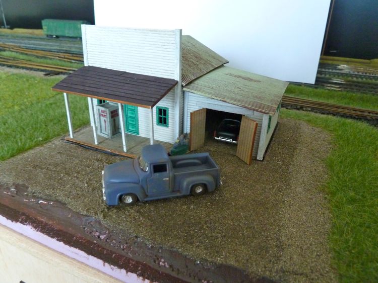
One of the things I "love" about shooting pictures of modeling work is how quickly you spot screw ups. That post, swear to god, was level. I now know I need to re-do it.
The roof was done in two colors; I'm going to let this dry for a while before touching it again with another green. I'm going for the rusted corrugated steel look. Note that it is not fixed or glued to the structure, hence the wobbly-bobbly appearance.
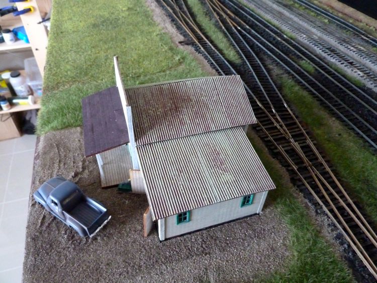
and one other shot, just for fun.
Overall, I've had some issues with this kit, especially with warping, and I think it could be better designed. Still, it only cost me $14, so I'm not complaining, it's filling this spot nicely, and while the look is a bit more Western, I'll keep it for now.
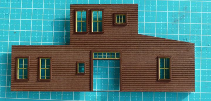
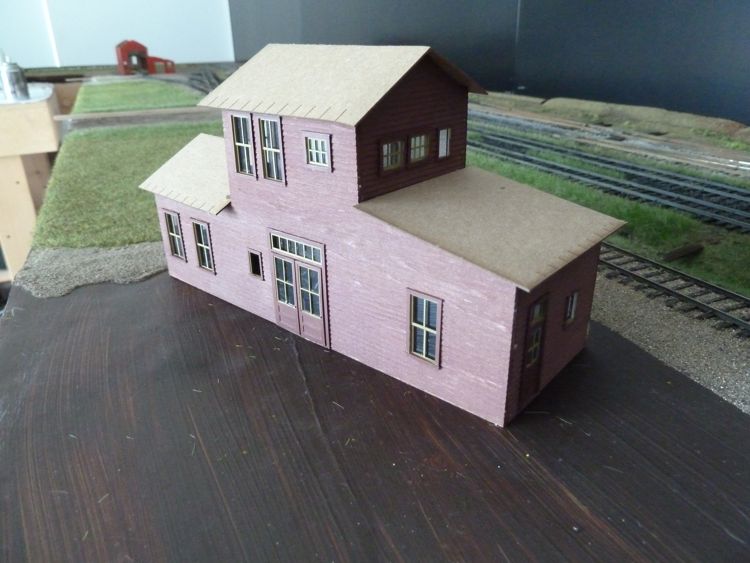
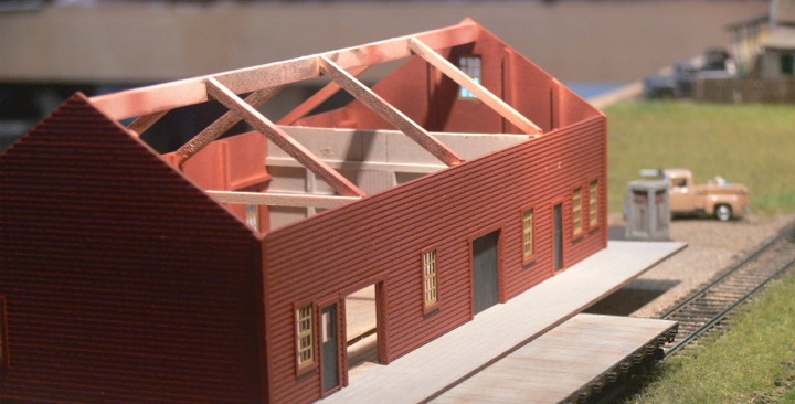
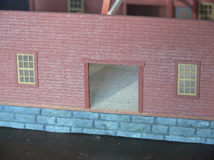
Building — The Freight House
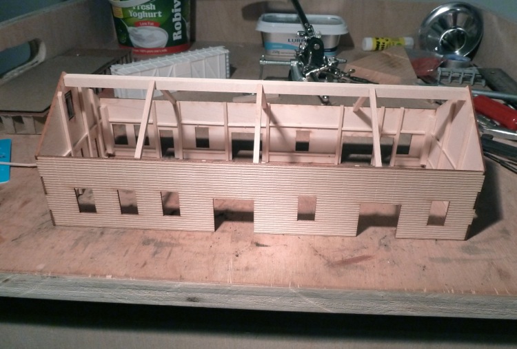
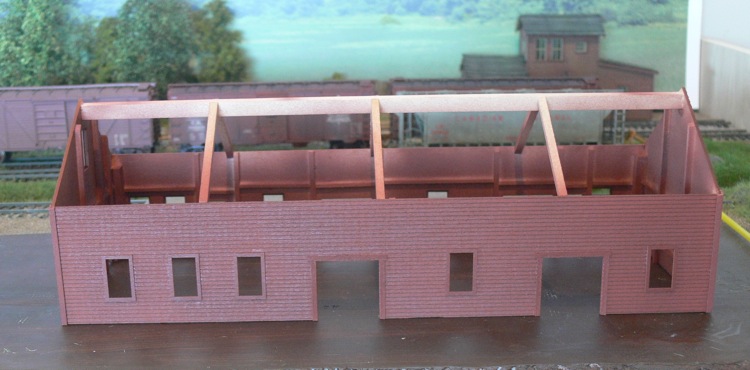
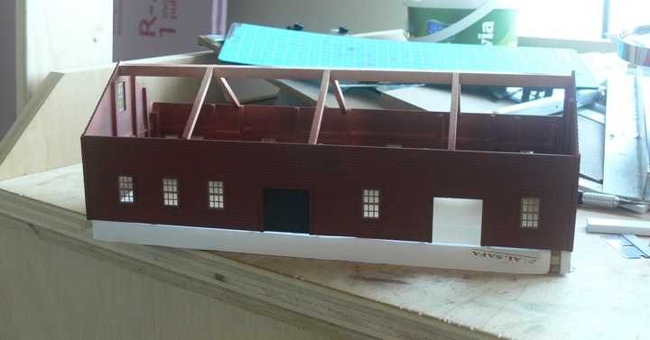
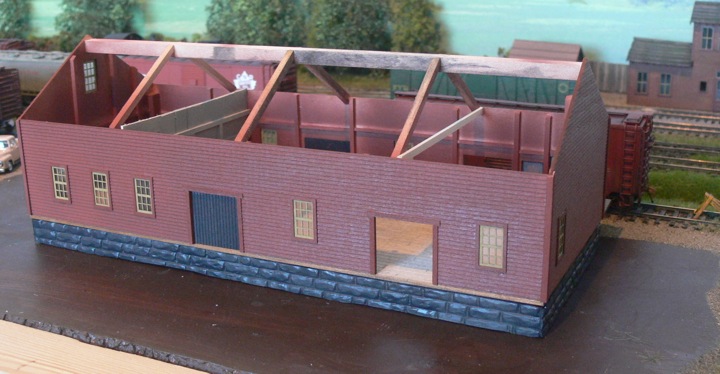
This is a laser cut kit, and the instructions varied a bit from other kits I've built. Most importantly to me, they specified that painting of the walls should occur after the main assembly.
I'm a bit concerned about this, due to the fact that I've had some warping problems (with the engine house on module 2, for instance) with this type of kit.
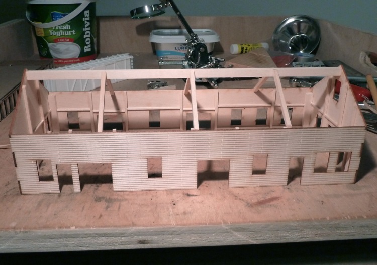
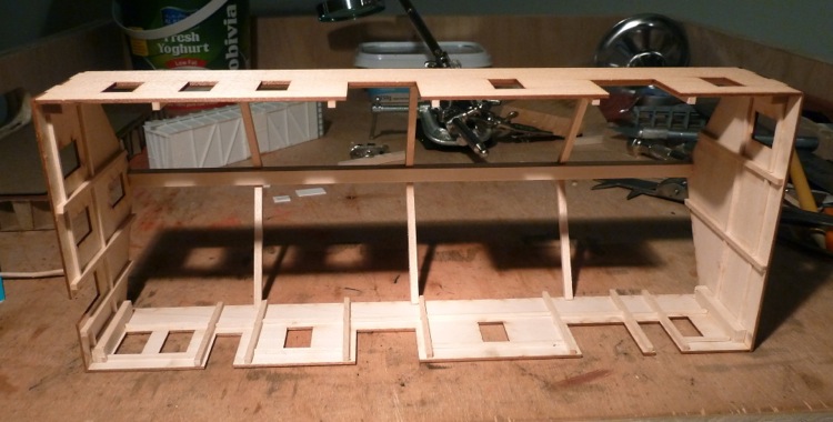
Due to my concerns, I added a fair amount of internal bracing to the model that was not specified, in order to minimize the chances of warping.
Painting will occur (inside and outside the model soon) with the airbrush, once the window and door frames are on, as they will all be painted the same color.
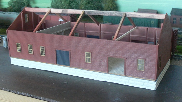
I spent a fair amount of time getting the window trim on, and than it was time for paint!
Did I tell you I love having a spray booth?
This is painted with a base coat of Polly Scale Mineral Red, and than a light coat of Badger CN Red over it. I chose to not paint it the DRGW Red that I used on the tower, as I thought some slight shade differences might be more interesting to the eye, as they will be sitting close together.
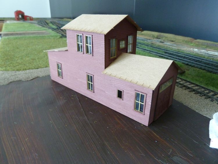
With that drying, I turned my attention to the windows and doors, and got them painted (Depot Buff for the windows, black for the doors) and glazed. With everything dry, here's how it stands right now.
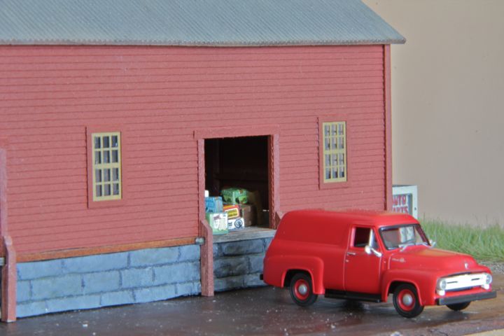
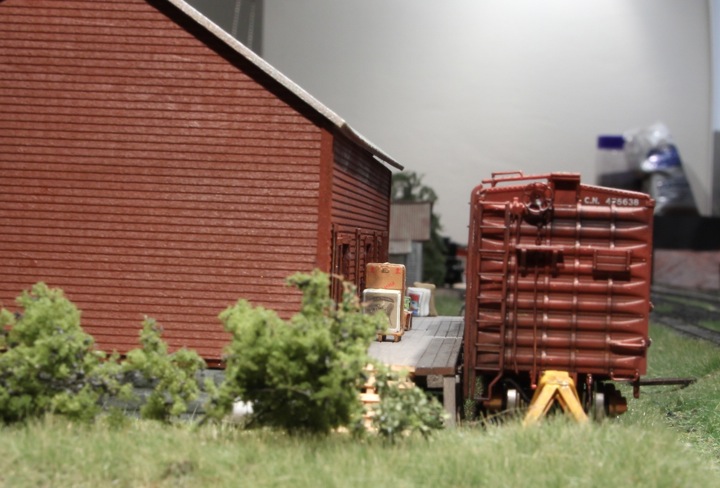
Two of the freight doors are off, as I'm intending to model them open. Which means floor, etc, and that comes next.
I'm really liking this kit, it's a great sized building for a layout. Big, but not overwhelming, nice at this scale.
Oh, and the warped walls...none. I don't know if it's because I used a spray brush, painted inside and out, added extra bracing, or all of the above, but there was zero warping, and that makes me a happy camper!
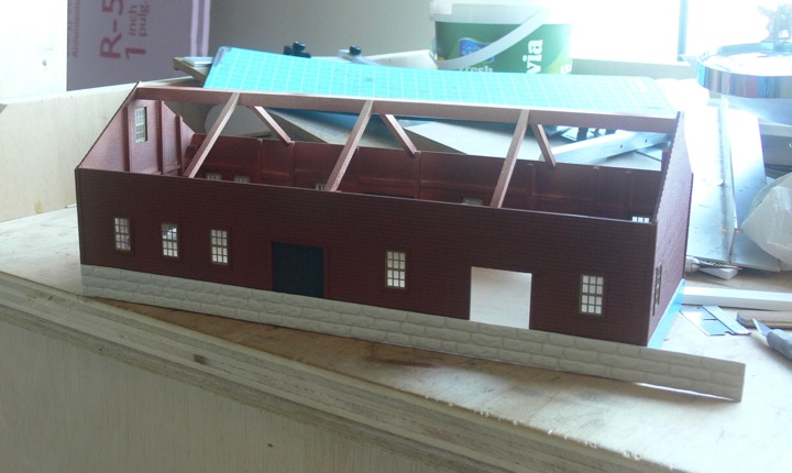
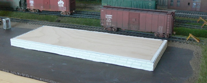
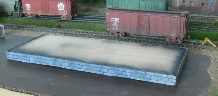
Meet the foundation of the freight house. The kit provides the modeler with enough material to make a mold to cast hydrocal, in which said modeler is to carve in rock shapes once dry. Four molds to be cast and carved, one for each side of the building.
These casts are a fair thickness, and go around a solid central piece of plywood (included). All of that sounds great, but hydrocal isn't that easy to find in these here parts.......
So I looked at an alternative method.
First up is to apply a ring of foam core around the width of the plywood to add the necessary sizing.
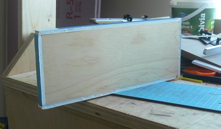
And check it for fit.
Next, was to measure and cut some of the plastic rock face that I've had with me from my very first chainsaw layout bridge abutments.
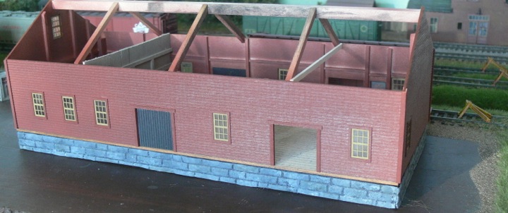
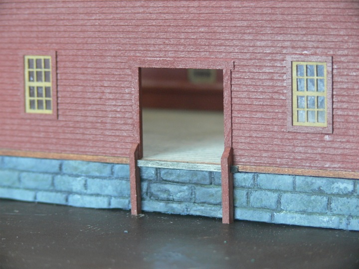
With a couple of sides cut and glued on, I turned my attention to adding an interior wall between the office and freight areas, and the floor. The floor was stained inside with ink and alcohol, than masked, and the exterior sections painted gray.
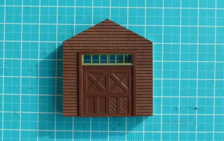
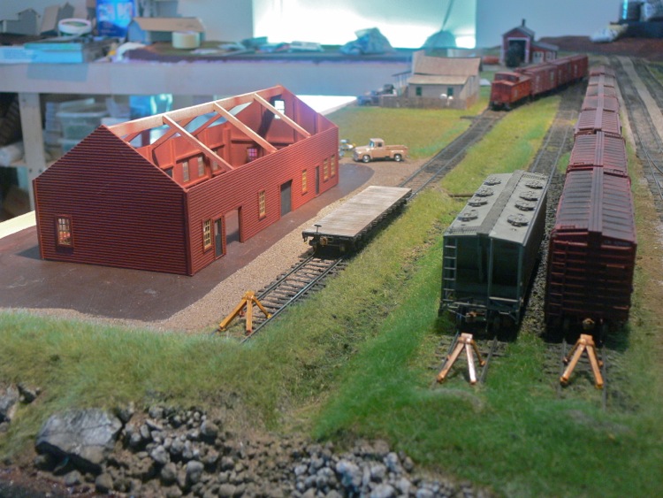
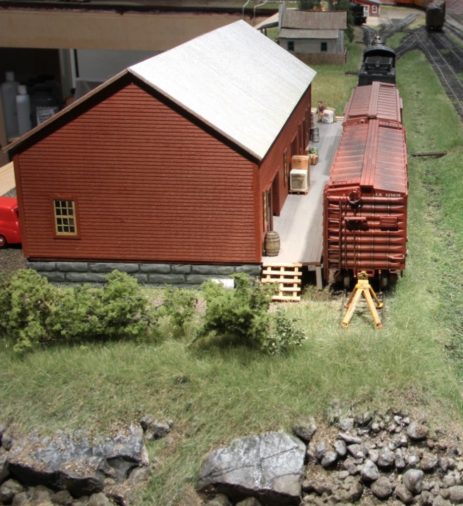
I am planning on having two of these doors open, on this end of the freight house.
The interior wall isn't meant to be detailed, but just work as a basic view block. I also added one rafter, as this should be all you'll see through the doors.
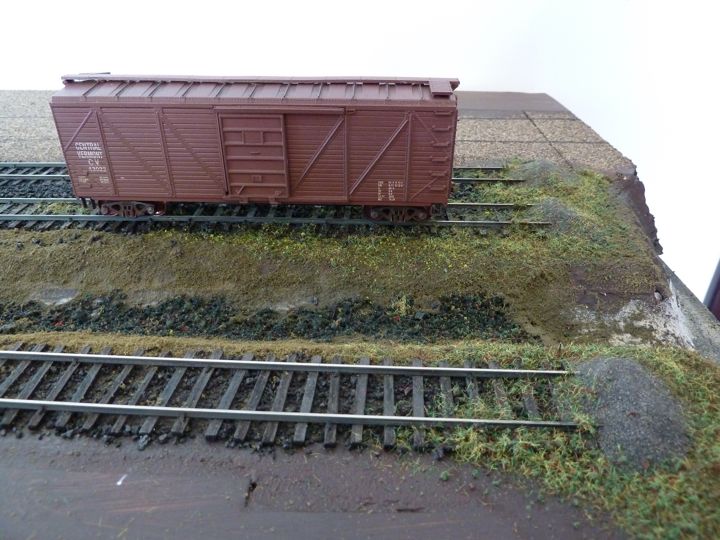
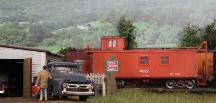
I think you can see the floor color change from gray paint to bare wood in the open doorway. Either way, the height of the platform looks good, if the flat car is any judge.
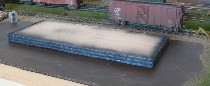
now to continue on the foundation... two more sides, than paint.
I found myself fighting with the foundation, mostly because the white glue I've been using to hold the plastic rock face to the foam just doesn't work well enough on the plastic.
I know, I know, Duh! But it's what I have, other adhesives are hard to find (back home I would have just used caulk).
After letting the glued face dry for a few days, the plastic would inevitably break off due to handling. When it did, it left a perfect impression of the rock face in dried glue. I than applied CA on that, and voila! The coat of white glue kept the CA from eating into the foam board, and it holds the rock face nicely.
That allowed me to fill the corners, and lay down the first coat of paint (black.)
Next up is to sponge paint the rock faces, as Marty M. demonstrated in the October 2011 Model Railroad Hobbyist magazine.
They key to this process, is doing exactly what Marty mentions. I took a look at my paints, and almost just fired ahead with some gray paint, but than I re-read his article, and instead set up some black and white on a palette.
It's the random mixing of those two primary colors that really lend to nice blending and color variation of the stone, not to mention the sponge vs brush technique. I'm sold on the process, and it gives me pretty much exactly the look I wanted for a base color on the foundation.
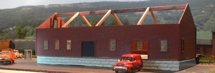
The foundation is now attached to the building. Before gluing, it got hit with a light coat of woodland scenics green base color.
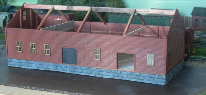
You can see the nice way the green sits on the stone texture, as well as a close up of the interior floor from this loading dock. I had "cut" board lines into the flooring prior to staining.
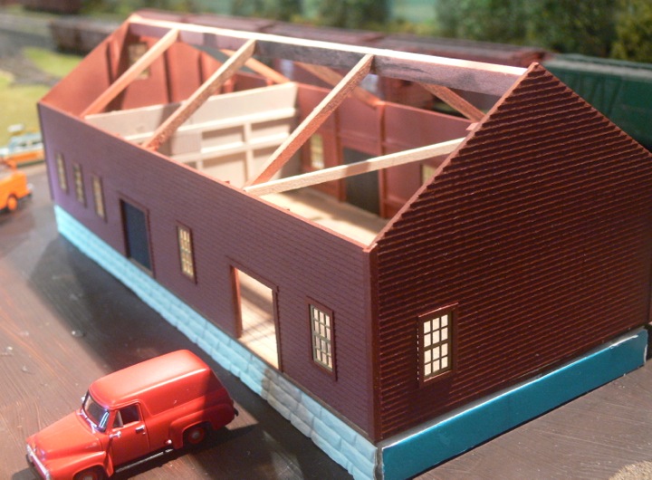
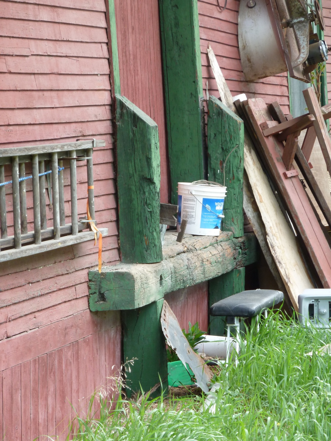
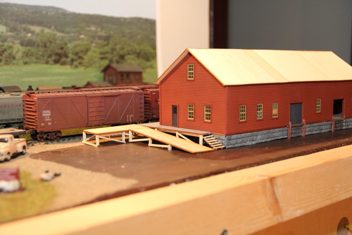
With the foundation now securely attached, I've been able to begin the rest of the work on the freight house. First up were the loading docks, based loosely on some prototype pictures I've taken of Central Vermont prototypes.
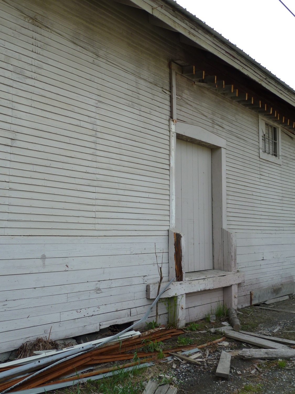
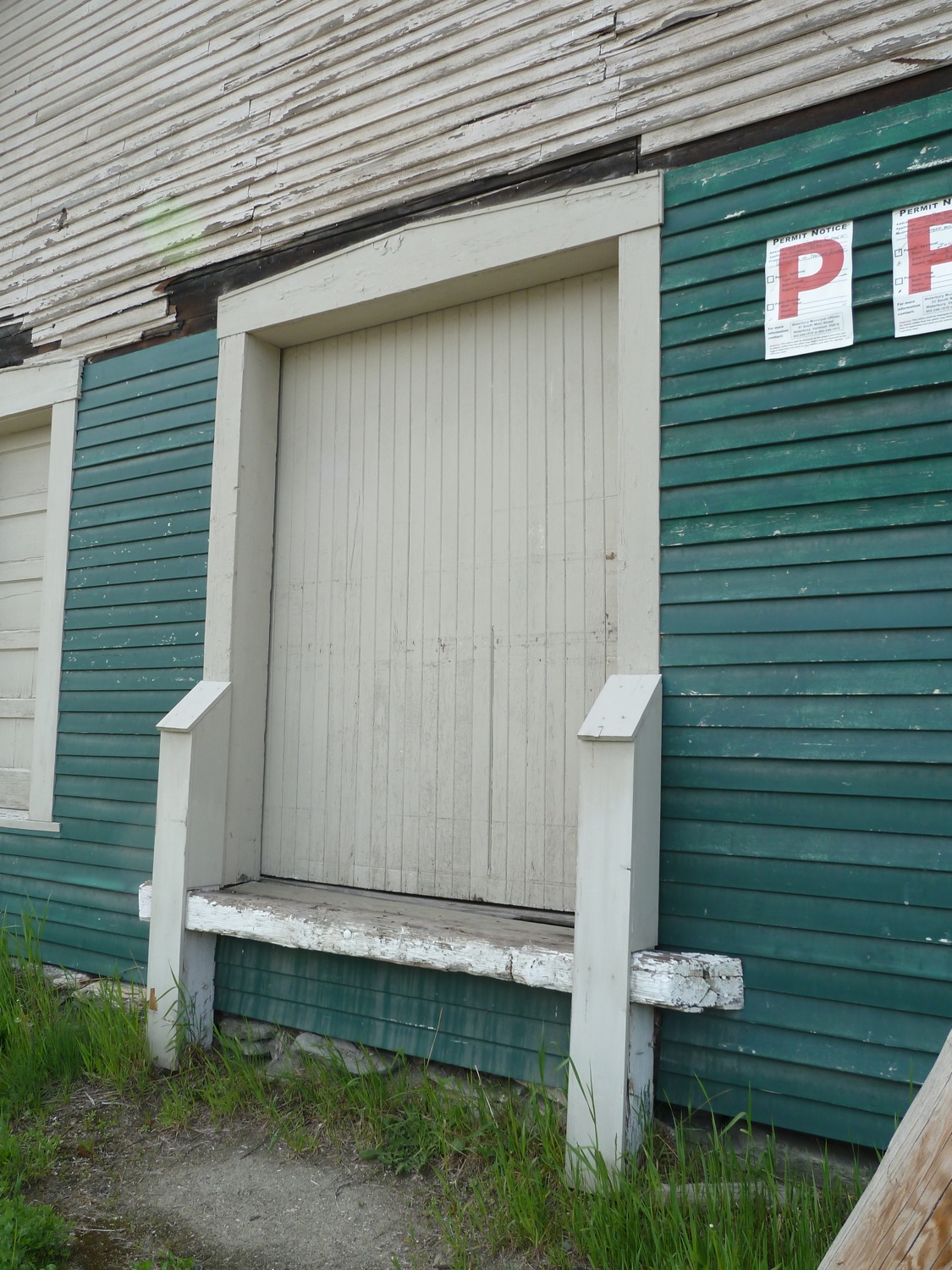
Based on these different samples, I came up with the following for the truck side freight doors on my house.
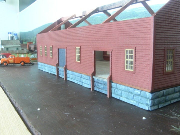
There weren't really instructions for the front platform in the kit, so I've just winged it (based on some other pictures I found).
The bottom of the platform was reinforced, and than these posts run across the front on 10 foot centers, and finally the cross supports. the extended post support is for the extension
The extension, with ramp. It's my intention on making this separable for transport purposes. I still need to do stairs, supports on the ramp, and some railings. Oh yeah, than paint.
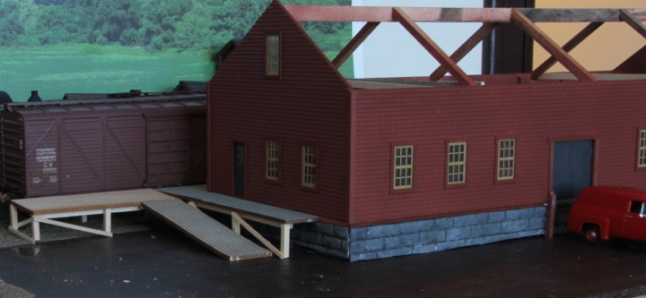
Finally, a quick photo just for fun!
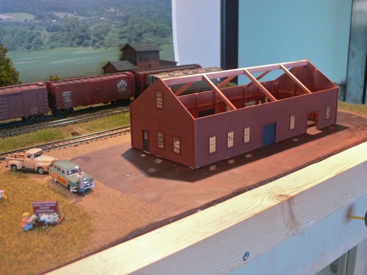
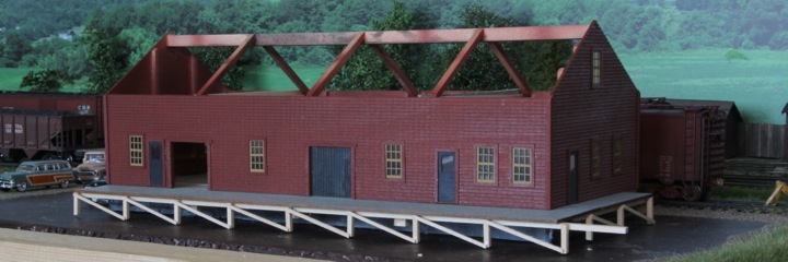
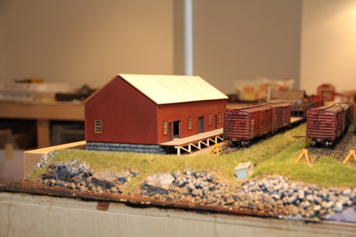
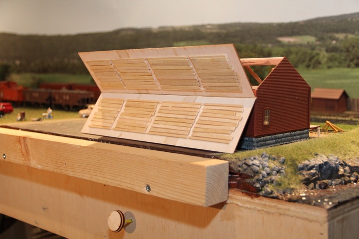
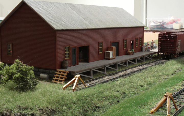
The side ramp and stairs are ready for paint, and the roof is now on...
But they are still removable. Note the coffee stirrers are gapped to allow the roof rafters to fit, but still provide lateral support (and join the 4 separate pieces that make up each slope of the roof).
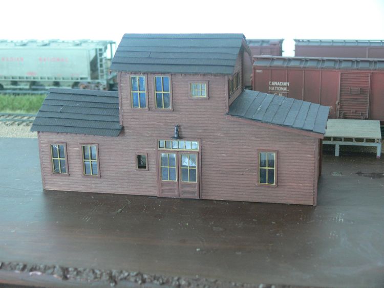
Getting a little closer every day, the base paint is up on the roof and railings; now just some detailing, basing, weathering - you know, all the little things that either take forever, or never get done!
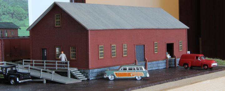
The freight house is about 90% - I see a few things I'd like to touch up, and i'd like to add some more vegetation and some details along the side, but overall, I'm pleased with the results - especially now that the driveway is done.
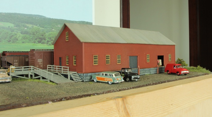
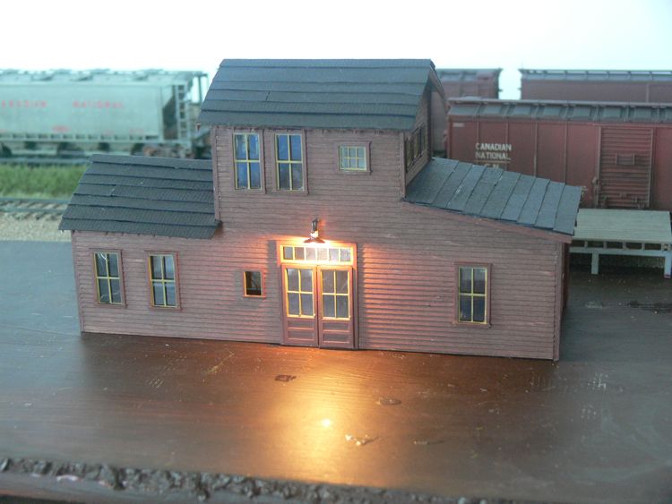
No lights yet, but I do have some better pictures of it in place. The lights are waiting for me to sort out how to wire the inside without it showing too badly.
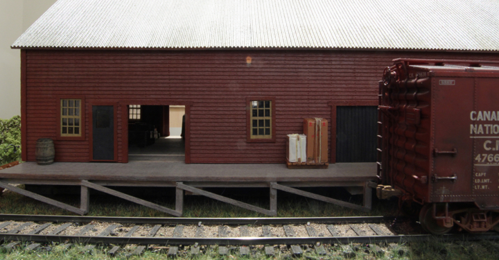
I'm not detailing the interior - but because it's in the front of the layout, it's not empty either. The roof comes off, and there are some crates and boxes that are visible through the windows.