Module 3
I wanted to work on some scenery first on the other two modules, but I realized that my track design left me short in two ways from an operational standpoint - a very short yard lead, and no runaround. This module has the other half of the run around, and enough track to extend the yard lead a fair amount.
I decided with this module to NOT delay months in putting down the foam board, and started the gluing process last night.
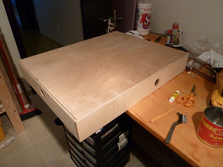
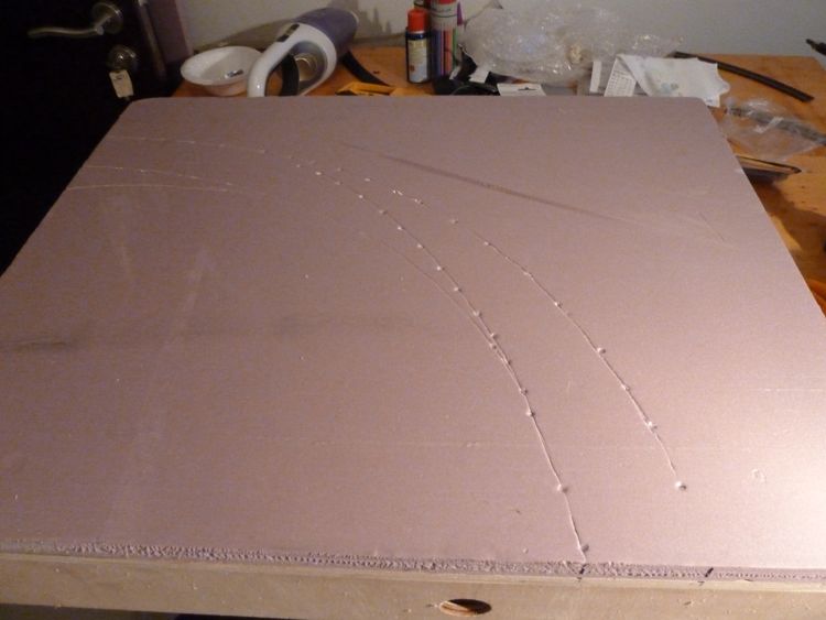
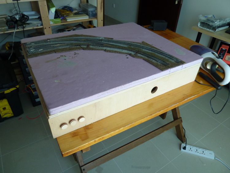
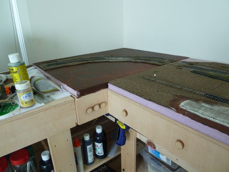
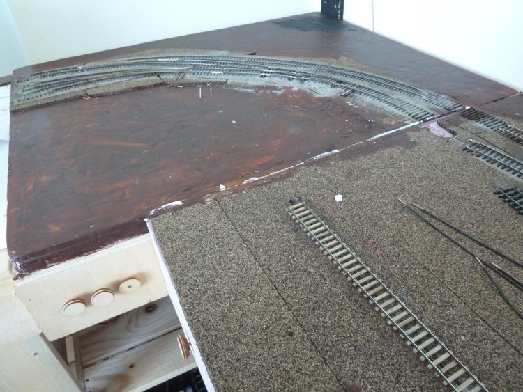
The bare module.
And the foam being glued in place.
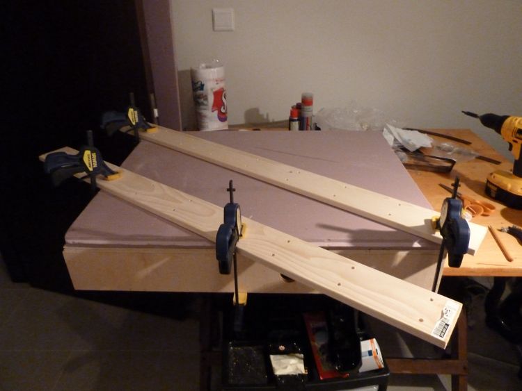
Sometimes, the best desinged plans.....can go awry....
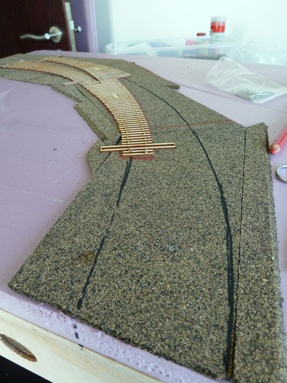
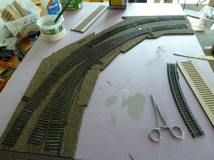
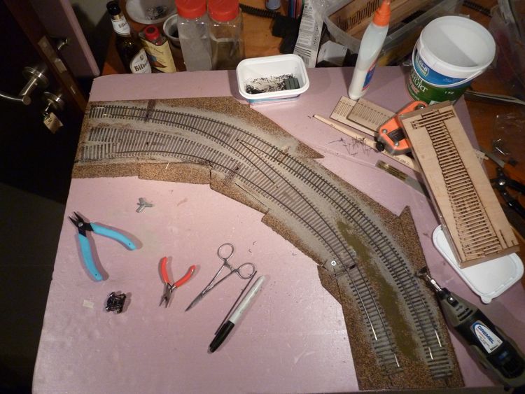
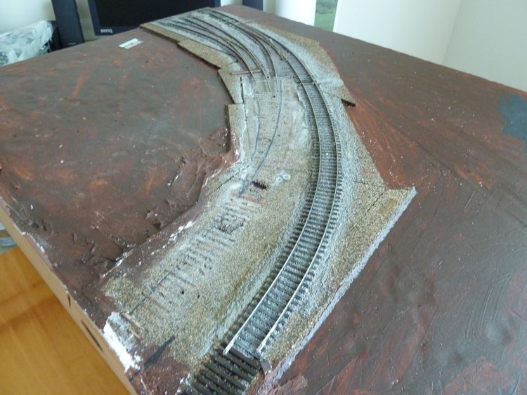
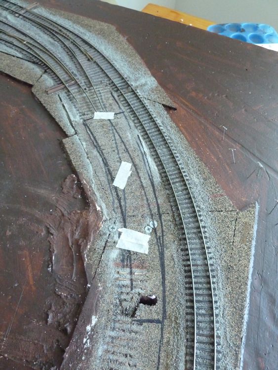
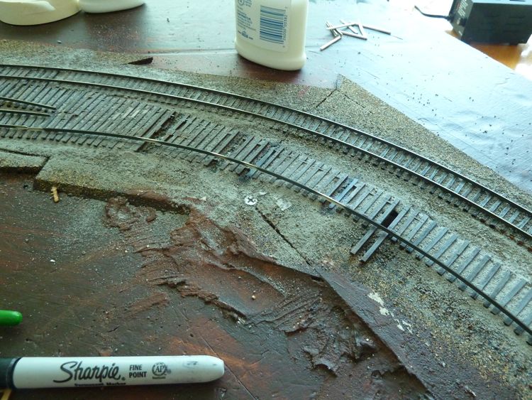
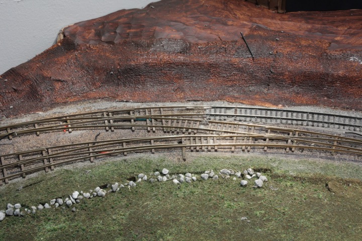
With the pink foam down, I placed the track template down, and lined it up with the entrance and projected exit points for this module (entrance points shown below).
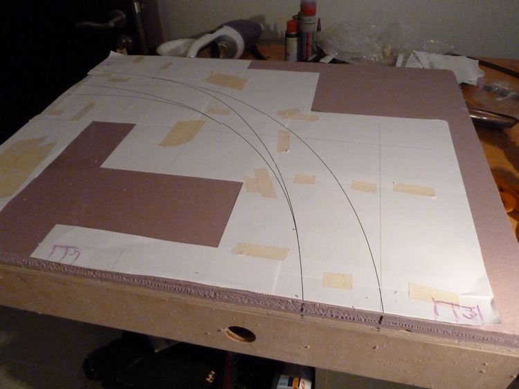
I started punching holes with my trusty red pencil, and than remembered that I had ordered ponce wheels from Micro Mark the last time around. I brought out the big one, and let her rip! (er roll).
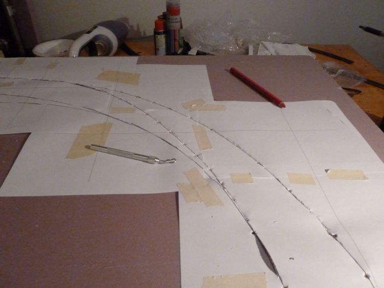
The ponce wheel did a great job transferring the plan to the foam......
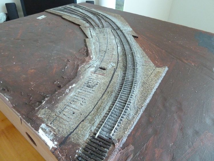
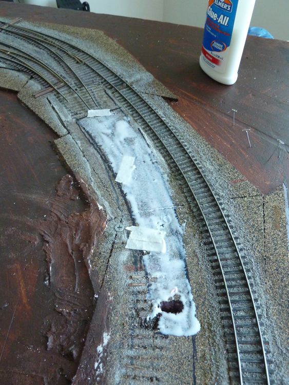
But, than I remembered that I had to put down cork first! So back to the drawing board, and I put down the cork roadbed.
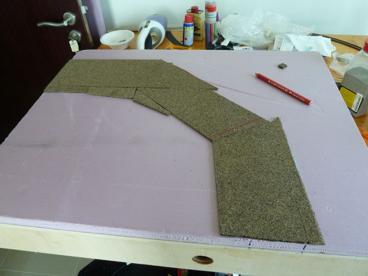
So....after that dried, I repeated the process with the track template, this time using a black marker to transfer the plan to the cork (the marker wrote through the holes the ponce wheel made into the paper.
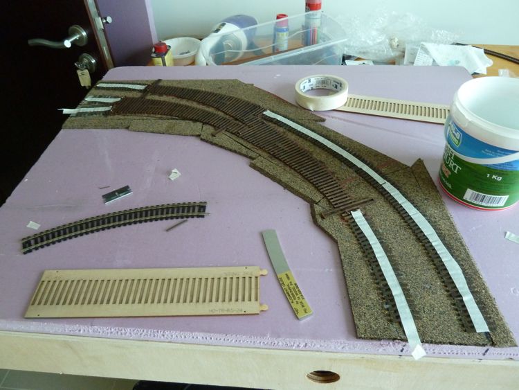
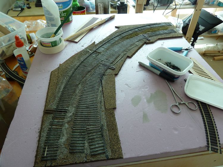
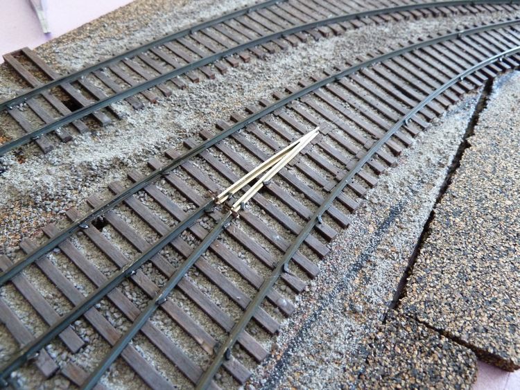
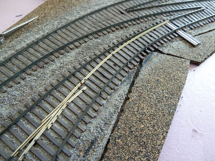
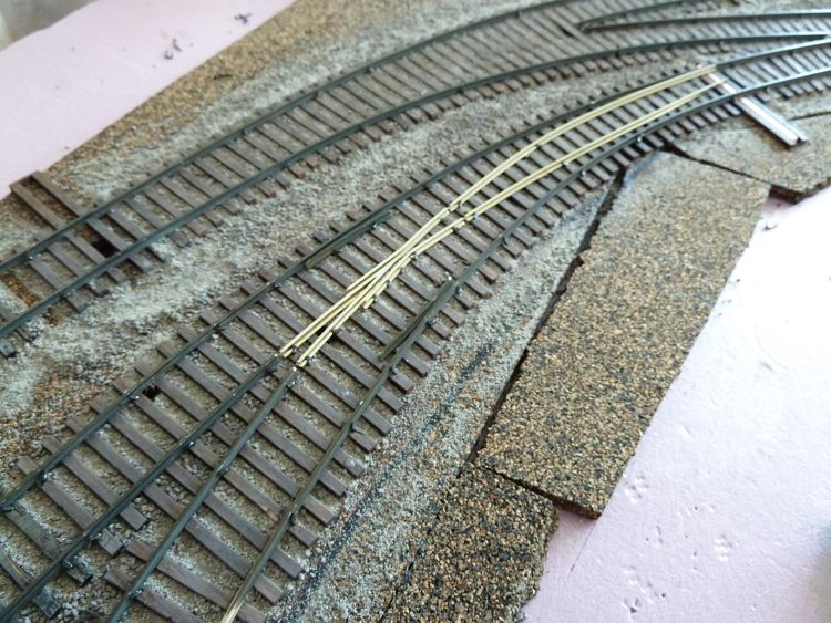
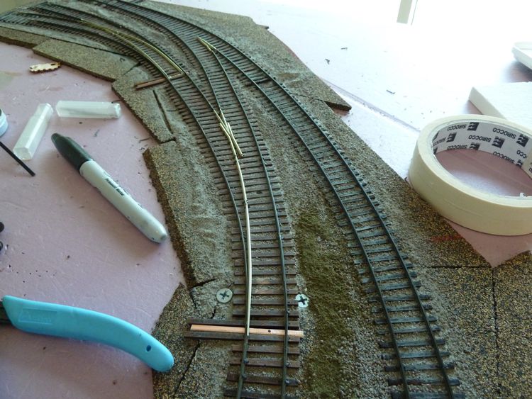
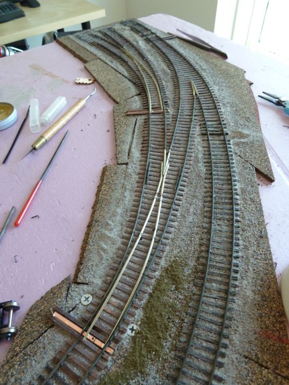
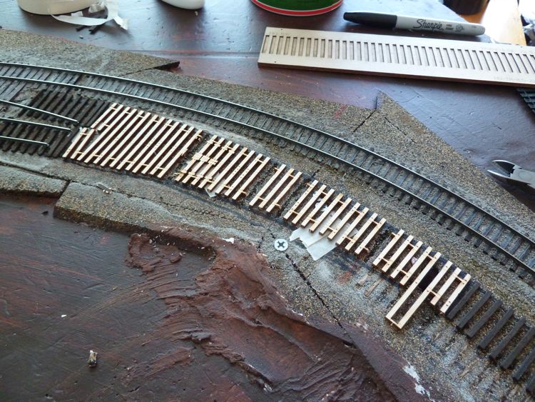
With that down, I pulled out the first of the Fast Tracks Twist Ties sets I had for this application, and pinned it in place.
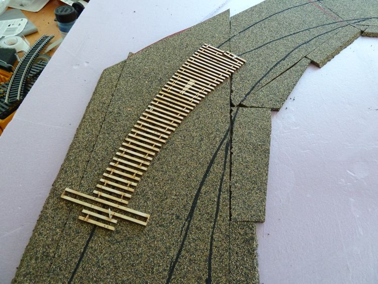
I chose the twist ties as I don't have a curved turnout template, and I wanted to build these up myself. I thought the twist ties, with their variable radius, would be useful for my first foray into building a turnout without a jig (and curved ones at that).
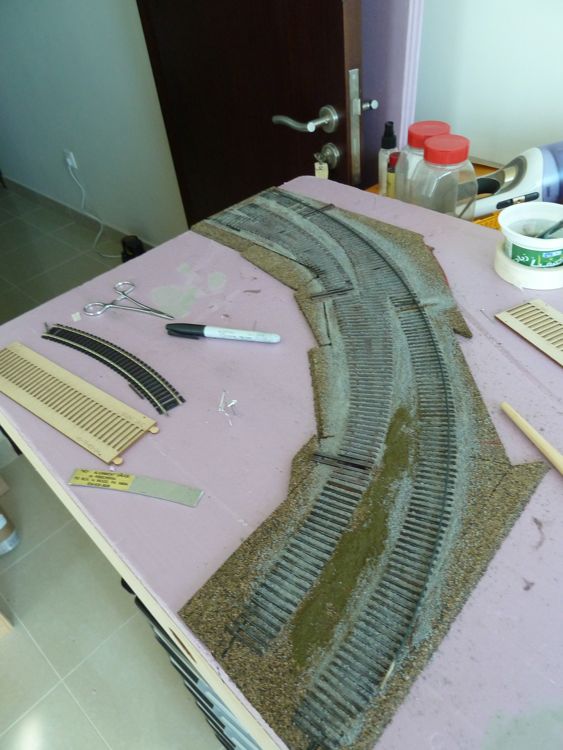
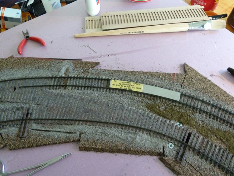
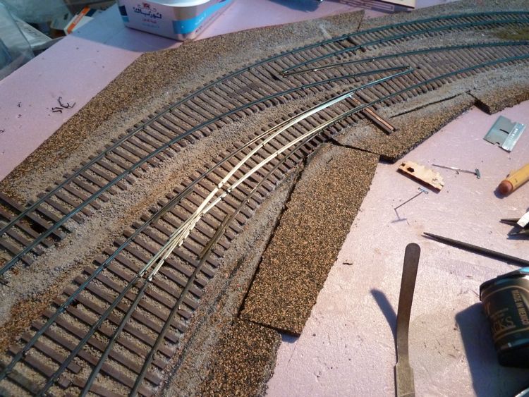
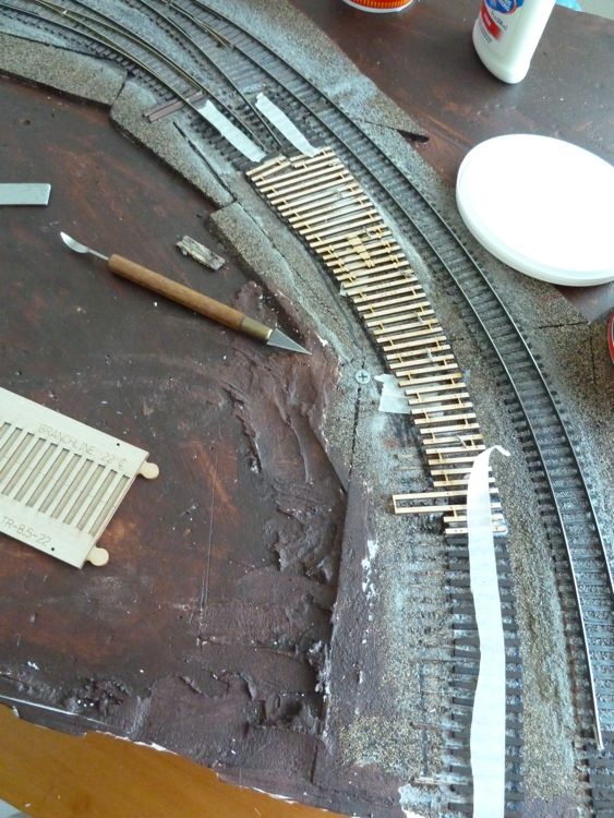
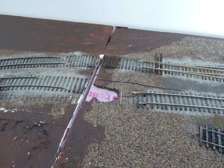
As I broke out the other two needed for this module, I came across immediate problems with the radii. See the 18r piece of Atlas snap track on the side, the outside track is supposed to be a 22r curve!
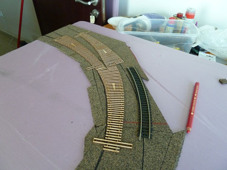
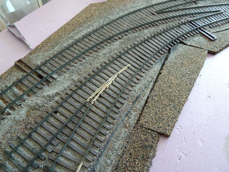
Playing with multiple variations I came to realize that I wasn't going to be able to follow my exact center lines, but I could get a workable curve and accurately meet up my entrance points (more important here than the exit points, as there is nothing on the other side yet to join to).
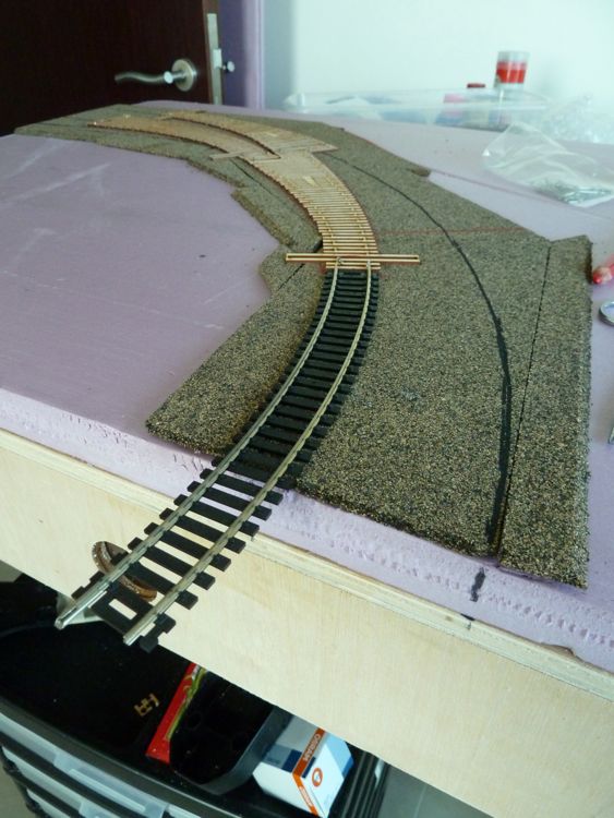
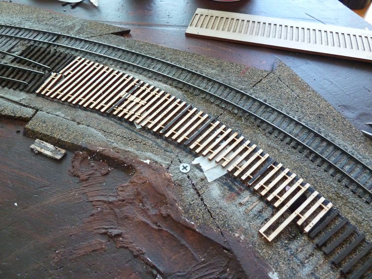
So the inside curve is tighter than I wanted, but should work (here's that nice piece of 18r Atlas snap track, showing how this should flow into the entrance point neatly).
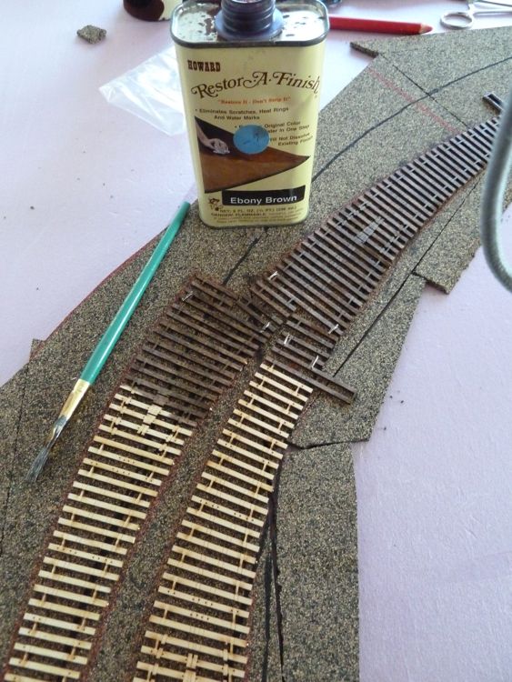
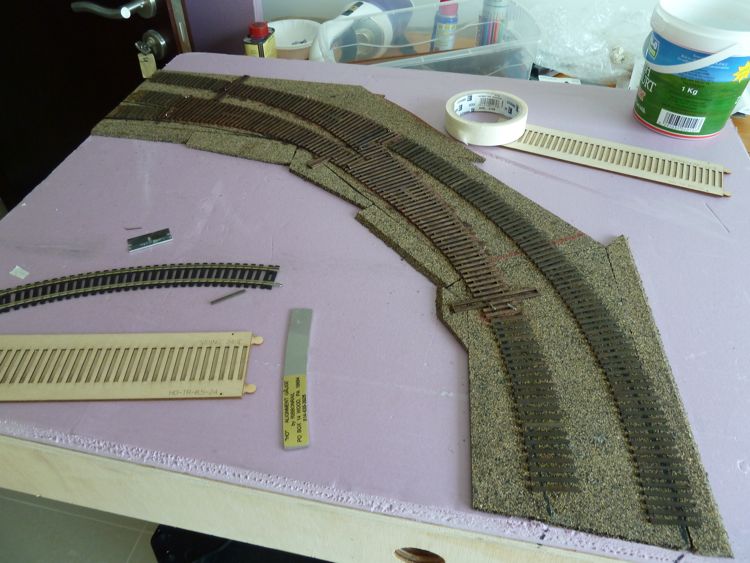
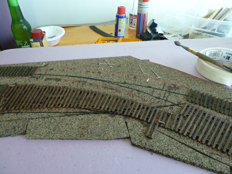
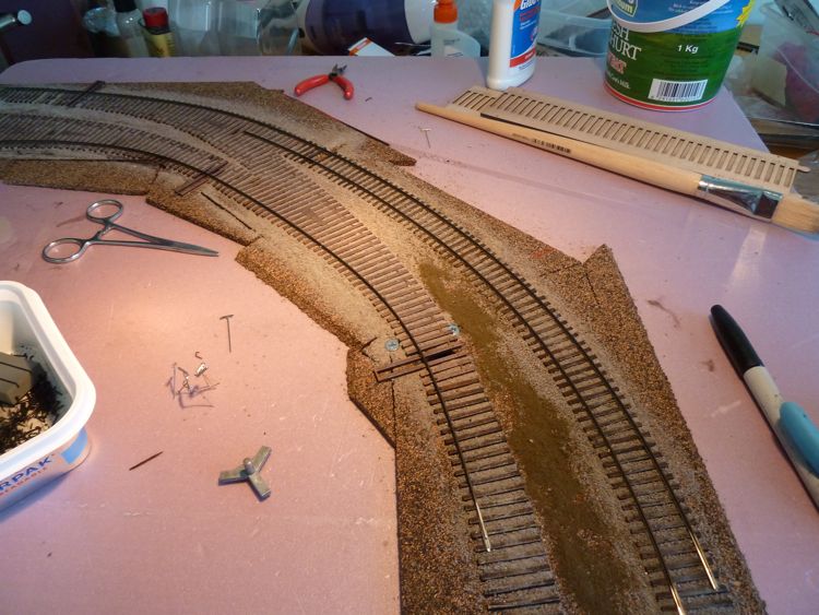
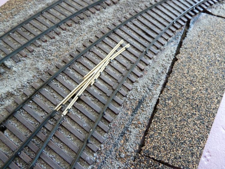
Leaving them pinned in place, I marked their outlines with my trusty red pencil, and than hit them with some stain. This is left over stain from a neighbor who moved here from Qatar and than returned top the states. I nabbed it, and upon opening it, was pleased with the color it provides as a base.
So once they dry, and the air in the train room clears, I can go back and drill throw bar and feeder holes, glue these down in place (as well as the rest of the ties for the module). Then ballast, and finally start laying rail!
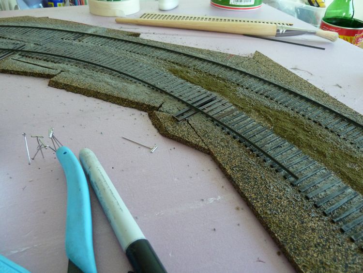
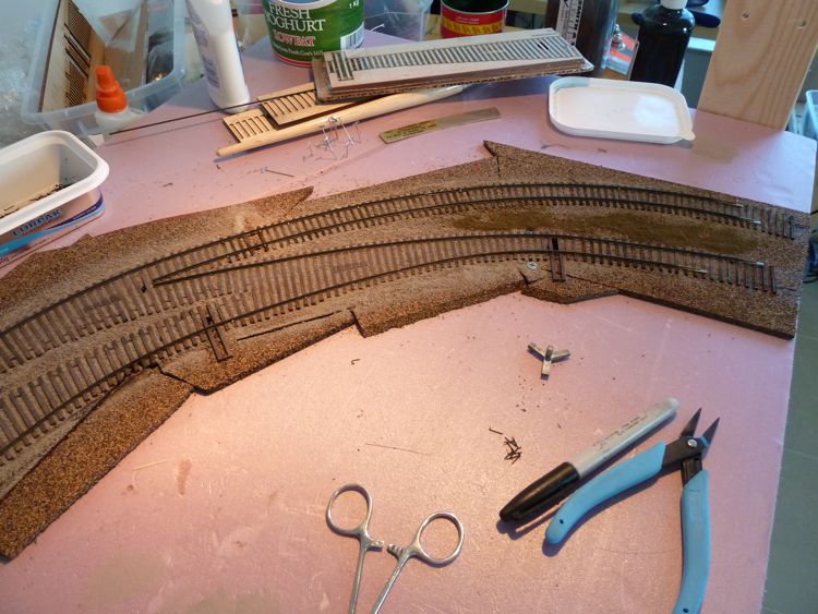
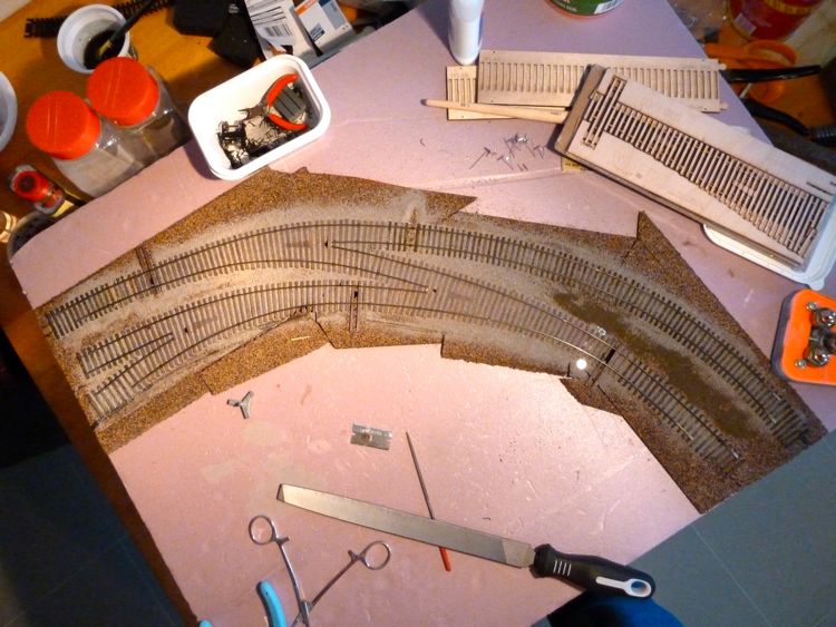
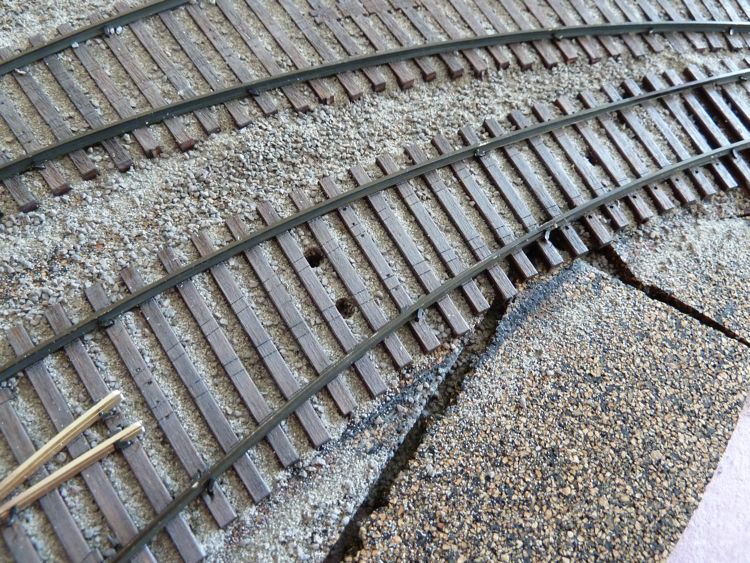
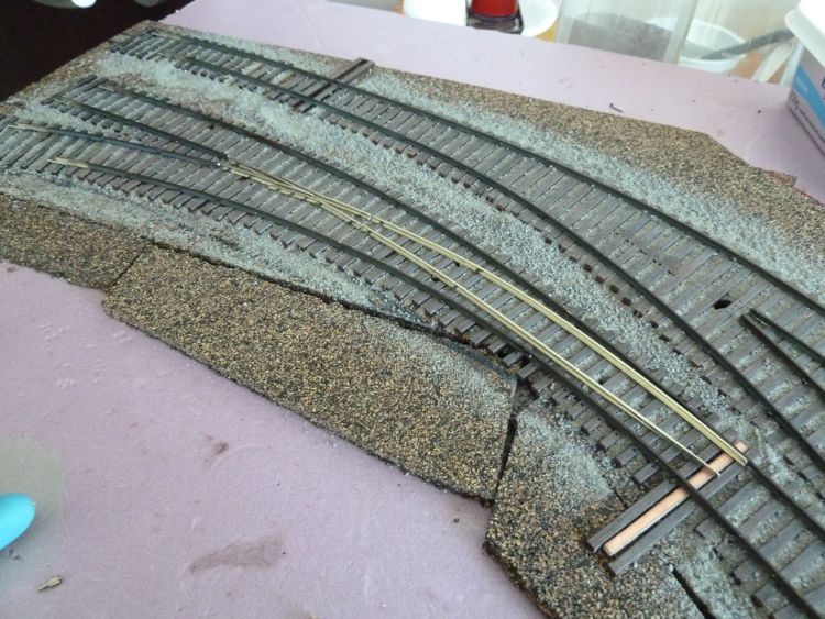
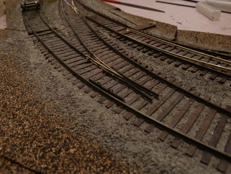
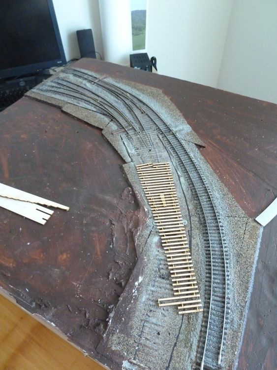
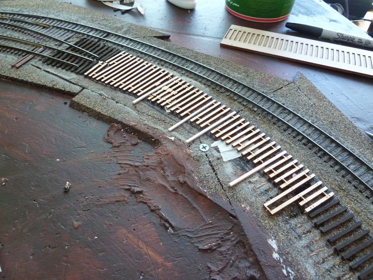
Before I can get to the rail, I need to get the roadbed work finished. And that means the rest of the ties down, weathered, and ballasted.
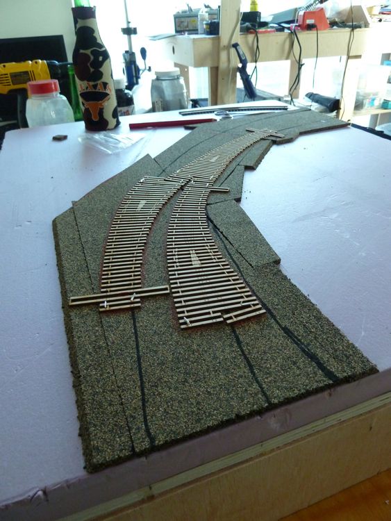
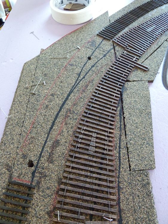
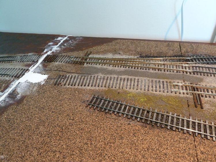
First up was the rest of the ties.
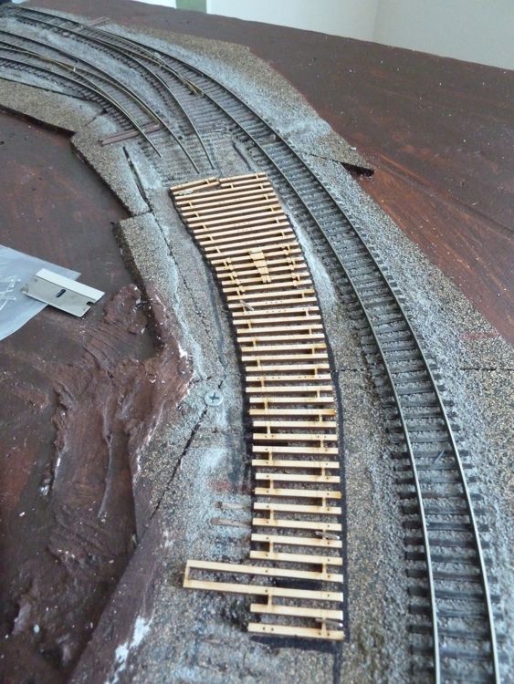
As I was happy with the alignment, I kept the turnouts in place (pinned, not glued) and aligned the cross ties to them.

Once dry, it was time to attack the turnouts themselves.
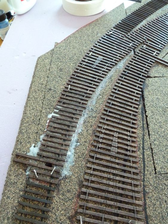
I decided to do just one at a time, and leave the other two in place with pins (again, to retain the alignment). I pulled out each turnout by itself, after marking the cork, and drilled the turnout hole and frog feeder.
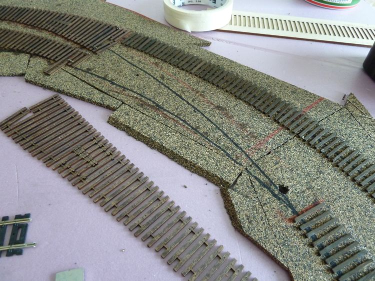
White glue brushed on, and the turnout ties pinned back into place.
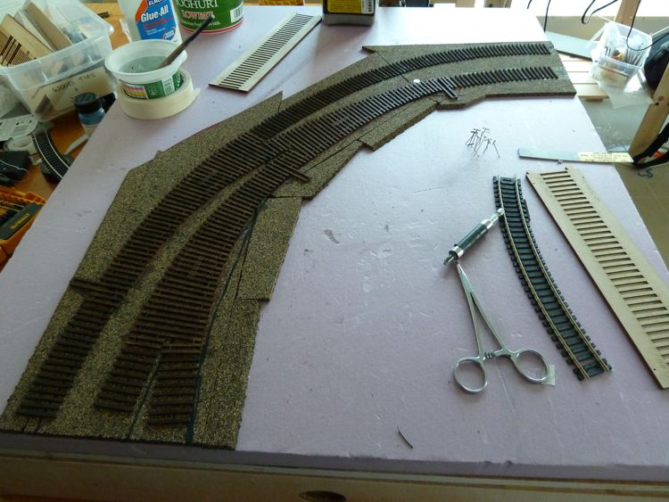
Rinse, repeat. Once that one was dry, it was time to pull up another. I use a couple of extra T-pins to indicate my drill spots.
I didn't bother taking pictures of the third turnout, as by now you probably get the idea. Finally though, all three were down and dry.
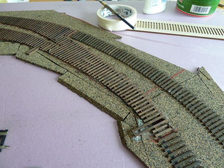
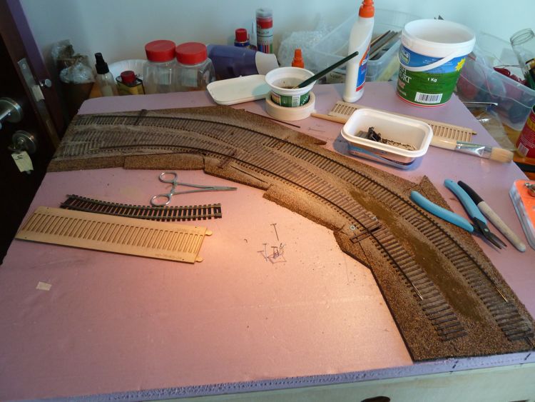
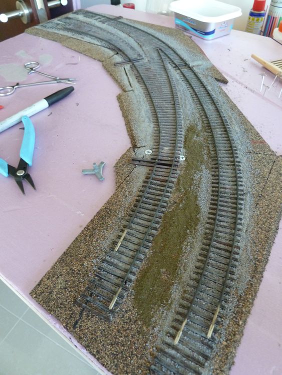
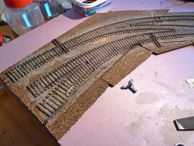
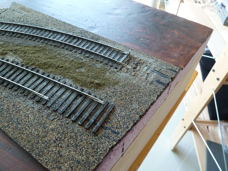
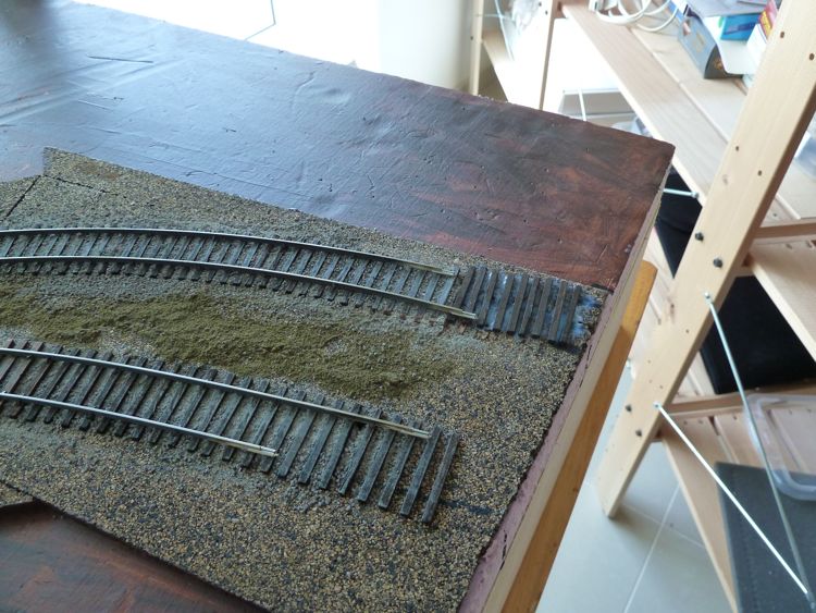
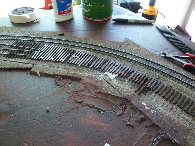
And than it was time to weather the ties with the usual dry bushed coat of gray.
Once this dries, it's time to drill some feeder holes, and put down the ballast, and than we can get put down some iron!
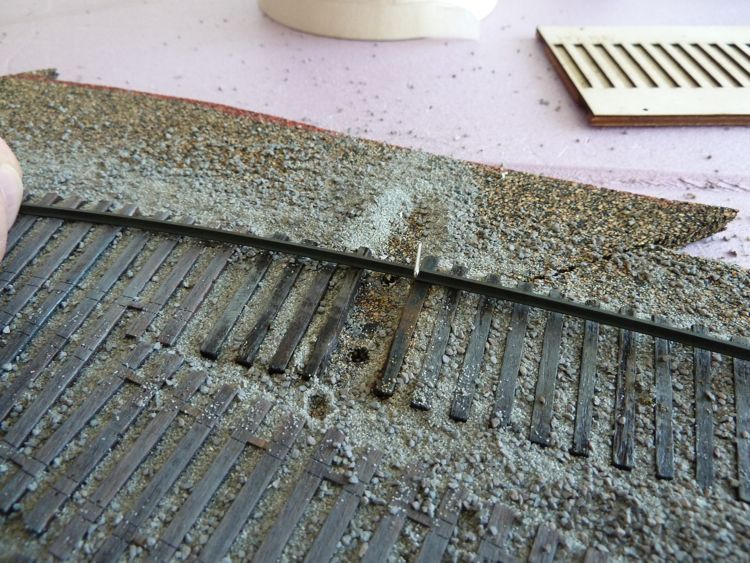
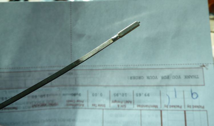
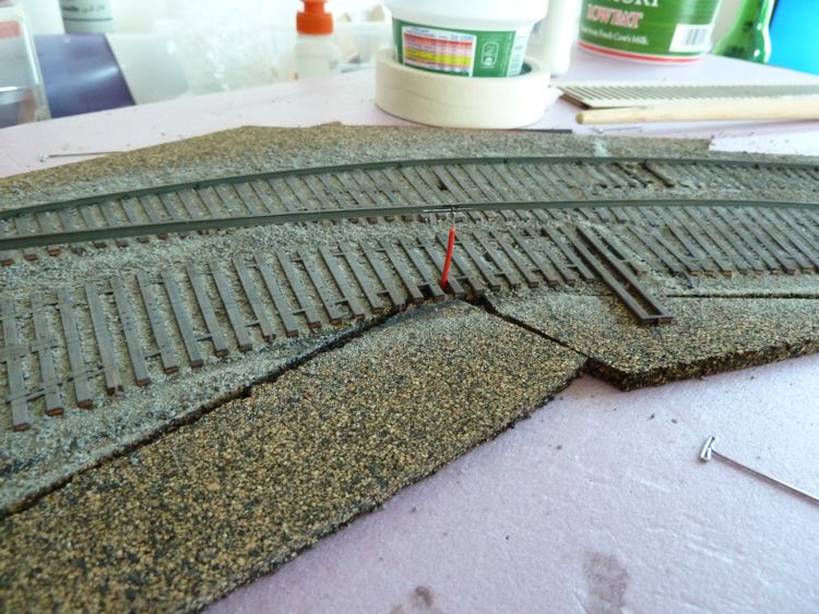
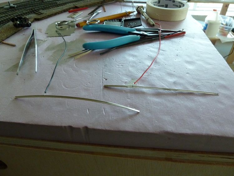
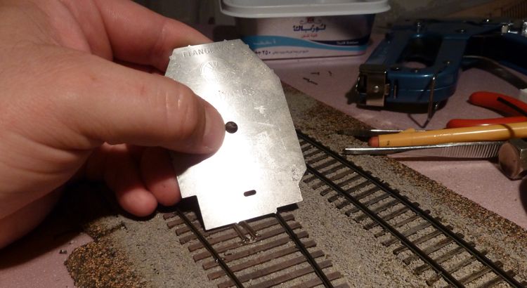
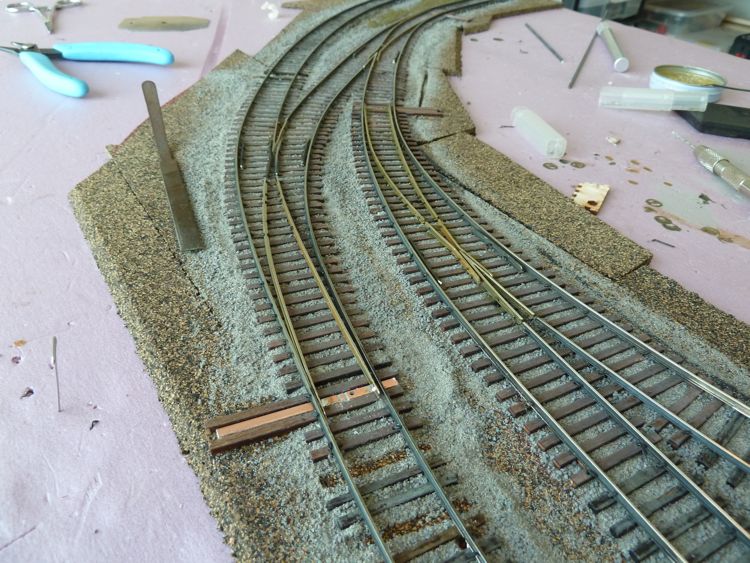
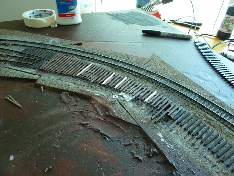
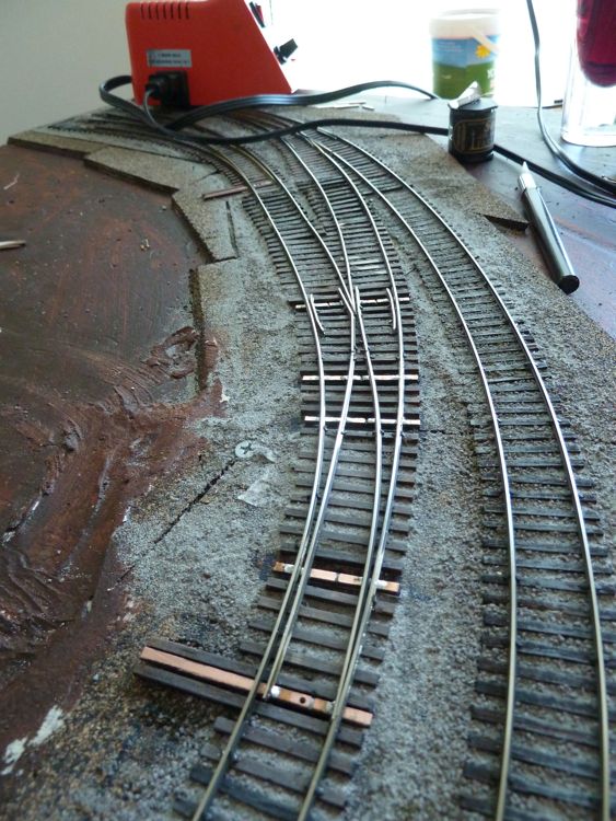
The ballast was almost dry enough, so it was time to work on the rail. First, I marked where the outside stock rail needed to have it's web cut.
Likewise, I marked the electrical feeder spot.
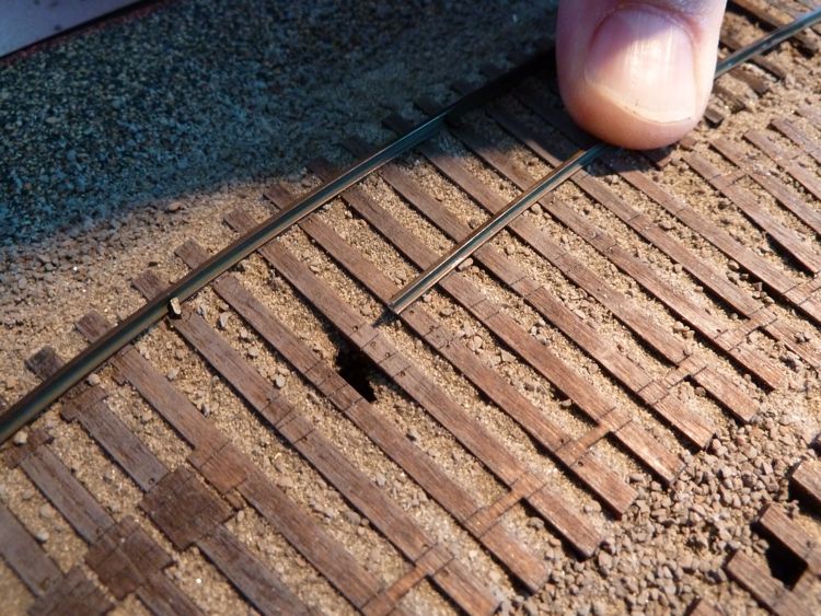
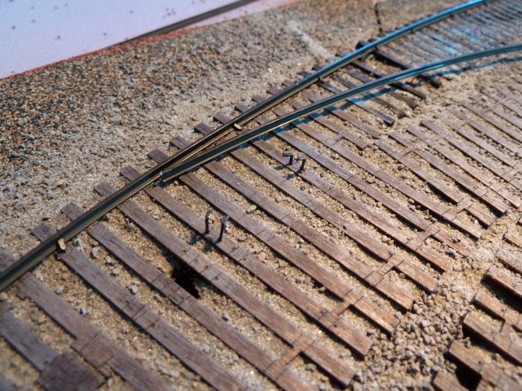
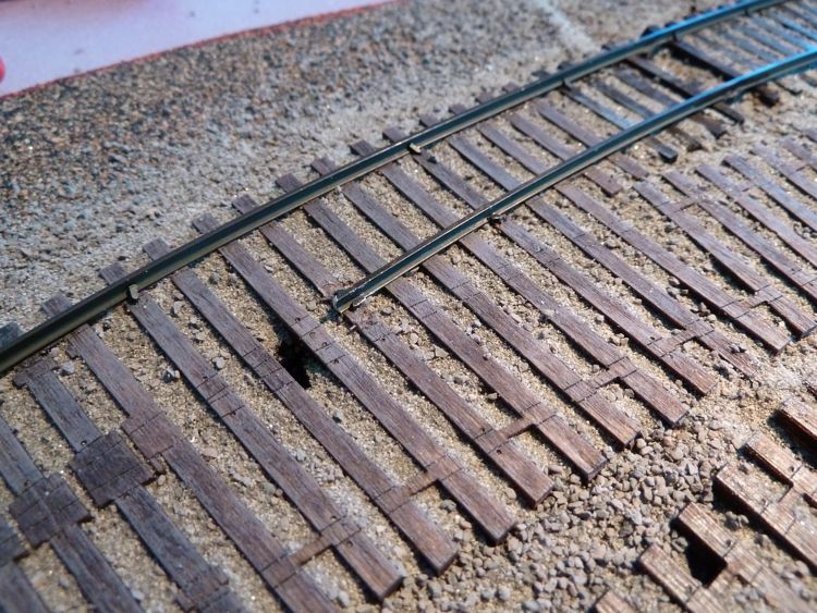
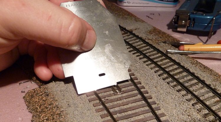
Once the web was cut, and the ends cleaned, I pulled out the Fast Tracks rail roller. Here it is in mid roll, I like to work it into shape, checking it against the actual needed curvature.
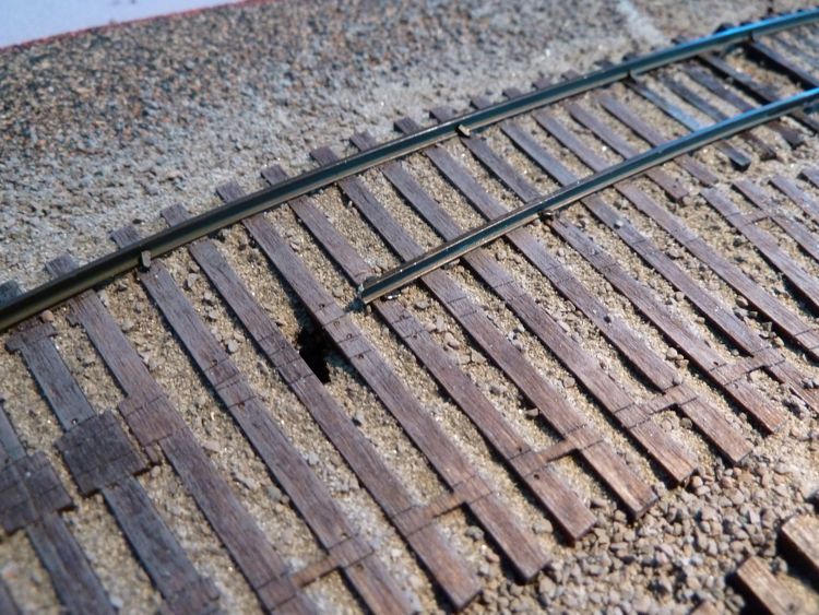
Once done, the rail now sits unaided along the track.
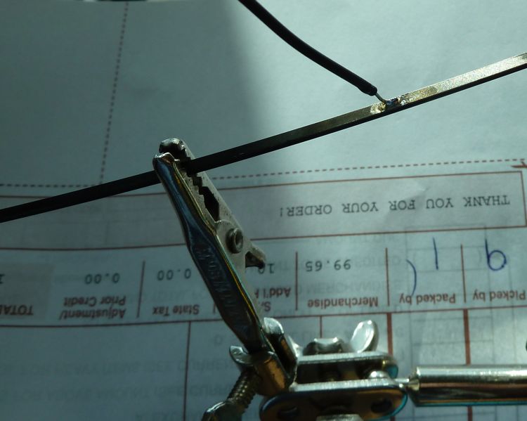
With the curve in place, it was time to solder the rial connectors and feeder wire in place.
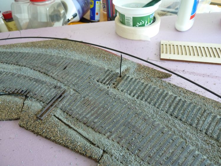
And than it's spiking time! First I slide the feeder wire in it's hole
Finally after spiking....I don't know if it needed it, but I added a couple of extra spikes in the turnout frame.
Two more rails went down, putting me a bit ahead of my schedule of a rail a day.
I started with the very inside rail of this whole set, as I had a trimmed piece of c83 that pretty much fit. Like the other, it was pinned in one end, and marks put down where the rail base needs to get cut for the points (two sets, as this stock rail will go through two turnouts).
Like the first rail, this one had the cuts, was bent, and than had joiners and the electrical feeder soldered on. I won't bore you with more pictures of the same, so here it is going down.
When finished, it was nice and tight. I have to say that the twist ties with the pre-drilled holes are good, I seem to never think the spikes will hold it and glue is needed, yet once I get them in place, they seem nice and solid. I did find that my holes on a couple of these were clogged, and best opened by twisting a spike around, in a back and forth motion, until it worked itself in place.
As that rail went down easier than I had expected, and so I decided to go ahead and do a second.
I don't like cutting gaps, I seem to have a lot of trouble with it, and so I thought with these, instead of cutting gaps after spiking, I'd simply cut them to fit and then spike them in place. For this rail, this point became the defining end.
No notching was needed for this one, just a bend, electrical feeder, and a single joiner soldered on.
In order to get this in place where I wanted it, I went ahead and drove the spikes in in advance along these points (they are twisted as I use the ME spikes, which have an oversize head. Due to that, I find myself twisting them into place after they get below the rail head height to hold the rail secure).
Ah, spiked in place. Nope, missed that one right in front, right on the edge!
Ok, got it on this one. It's down nice and tight.
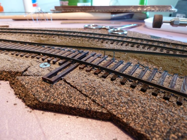
With that end secure, it could walk the rail back along the line, spiking as I went. A couple of folks have inquired, so I thought I'd share this basic technique on hand laying - I use the ME gauge to hold things in line, and than drive the spikes. Due to the oversize heads, I find it easier on a lot of rail to drive the spike in at an angle, as shown by the aspect of the spike on the interior rail. You can't do this with the Twist Ties, as they have nice, perfect,vertical holes, making twisting a better option.
15 minutes, and done.
I run an NMRA gauge over it, and than naturally run my test car. No problems (so far).
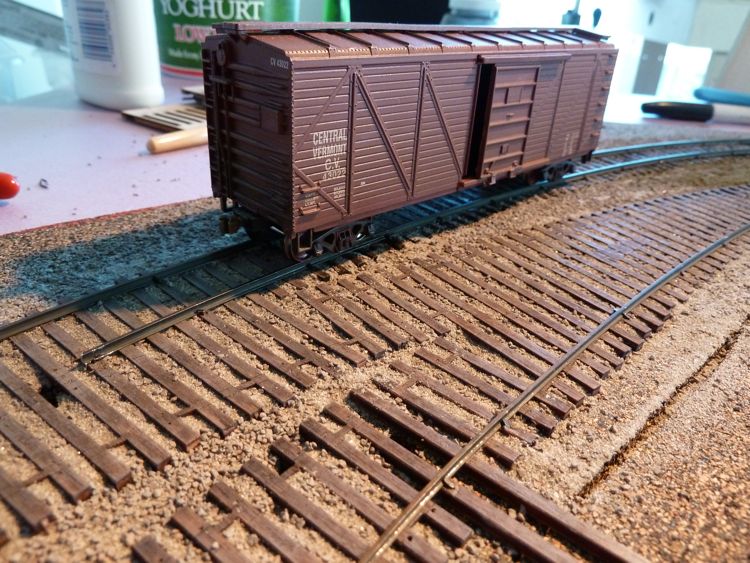
I went back and checked the radius using a ribbon rail flex track alignment tool. I had purchased this long ago, but find it still comes in handy. Looks like my work is just about a perfect 22 radius; I can live with that.
First was this one - for the first 90% things were going great!
then I realized that I hadn't cut the web base for the points! Duh! I was working from the frog of the other switch back to this one, so I started pulling out spikes in reverse until I could get it up enough to cut the base with a Dremel.
so with that fixed, I was able to put it back down for good.
I walked away for a bit, and came back. Working slower this time, I was able to get a second rail in place without a major mistake.
And the last couple of rails.
In this corner, weighing in at code 83, bare rail....
Round one.
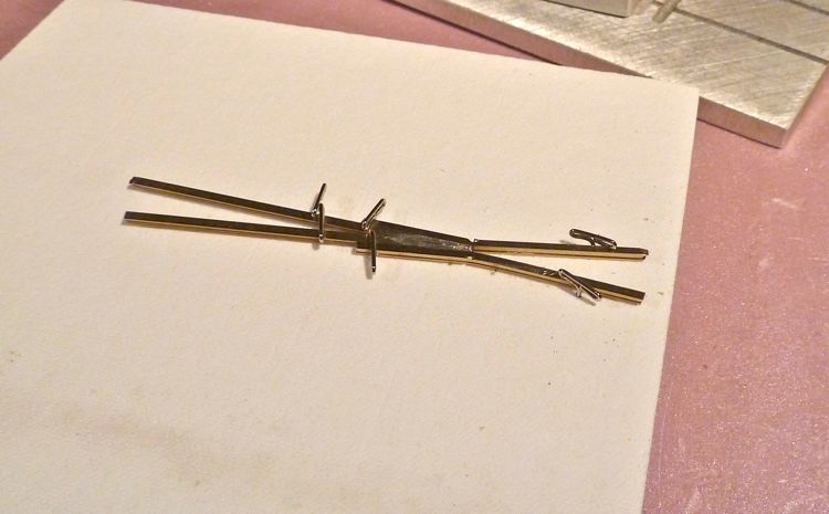
My plan is simple — to make a one piece frog that can be wired.
Started out just making a basic from in the jig.
I cut the other two parts of the frog, and flipped the whole thing upside down. I aligned them, pinned them in place, and soldered the rail bases together.
But I hadn't pinned it well enough, and the original frog solder job slid apart. So, back down, this time with enough pins to hold it securely.
Flipping it right side up, it looked good. But only at first. There is insufficient gap between the rails for wheels, among other things.
So I broke it all apart, and tried again - this time from the top; and dropped in a lot of solder into the gap.
But that failed as well.....Round one goes to the rail. I quit work on it to do a bit more research, and build up some more patience on my part.
My next approach was to use a small PC tie, my idea was to solder it up nice, than grind off 95% of the tie from below.
That worked, actually, leaving a nicely shaped frog with connectivity.
I trimmed off the ends of tie nice and flush
This does leave a nice clean path inside the frog.
but naturally, it broke apart as I tried to carefully remove the frog. I gave some real thought to just cutting out the wooden tie in the area this goes, and might consider it in the future, but for now, this isn't going to work.
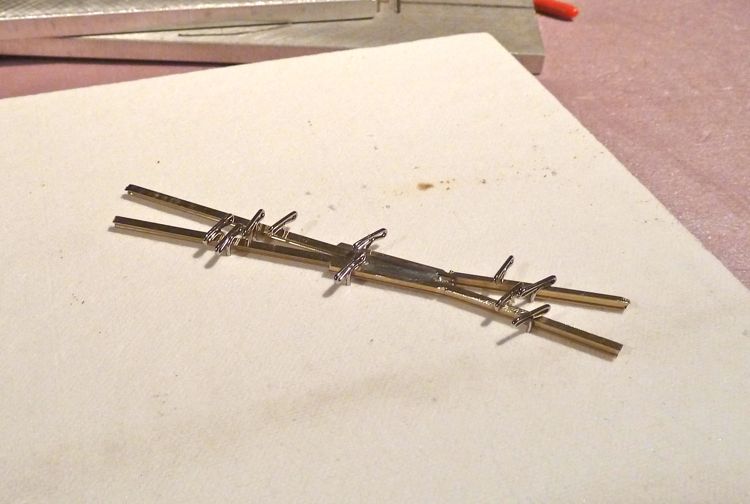
So for the next try, I thought I'd do the opposite - solder some wires on top that would be removed in the end. The top wires would work to keep the frog in alignment while I solder wires on the bottom to fit between the ties, the bottom wires could provide both alignment and conductivity.
Here it is with the top temporary wires.
as things were progressing well, I thought I'd check it against an unused twist tie. This helped me gauge where to put the bottom wires.
Flipping it upside down, I went ahead and soldered the bottom wires.
and than I removed the top wires. Success!
Until I cleaned up the top of the rails, and the soldering broke apart. Ah, sweet, sweet failure.
Again, this idea may work, but I got frustrated, and again walked away from it again.
After the appropriate mourning period, that included some more reading, I came across a trend in all the articles/posts/books on doing this. Building it in place.
Ah ha. Well, if you can't beat'em, join'em.
So I started with the frog, cut the guy to fit, and soldered the frog feeder wire in as well. There was some slight bending of rail needed before spiking, but with spikes in, it holds nice.
Next was this side of the frog.
And than the other.
It makes for a very tight frog, but seemed ok. Encouraged, I charged forward, soldering iron and file in hand.
I remembered from another post a comment on needing a feeder wire on the points, as the mechanical contact wouldn't be good enough - as a result, two new holes were drilled.
Down goes the first point, feeder and all.
And than the other.
The guard rails are very necessary on these turnouts, so they were next.
So I soldered up the throw bar to PC tie, and lo and behold,it didn't work. The test truck derails on the diverging route (it's ok on the other) in the points, I think the problem is I didn't bend the points enough before mounting them. As this is a curved turnout, I think the curve of the points needs to be exact, which mine isn't.
Of course that means removing the offending point and re-doing, but I think I'm on the right track. Pun, as bad as it is, intended.
I realize now how important the curved aspect is - I don't mind re-doing the point rails on this one, as it's a working model. It was disappointing to have it not work the first try.
I didn't think of rail creep per the gaps, so that's good info. I wonder how much will be reduced by the fact that the feeder wires to the rail will limit their travel. Still, I may fill the gaps with plasticard just to be sure.
I do think the PC tie method is superior for many reasons over a more traditional method like this, for exactly the reasons you mention - electrical connectivity, and permanence. That having been said, I am determined enough to try and make this work - if I simply cannot get this first one to work to my satisfaction, than I may begin pulling up ties on it and the other two and substitute in the copper.
There are pre-drilled spiking holes in the Twist Ties; if you build a frog set in the jig, the gap is significantly wider, and the rail base covers the pre-drilled holes. This can be overcome by drilling new holes, but I thought I should mention it.
The issue currently is with the points; I removed them, and bent them into the right curve. The NMRA gauge is perfect until it gets to the end of the point (near the throw bar) where it's simply too narrow; the outside rails are in the right location, there is simply no place for the point rail to go.
I suspect this is due to the sharp curve I've created. I'm going to file down the outside of the point rail base along a full 1/3 of its length, to see if that gives me the room needed for it to be within specs.
I got it!
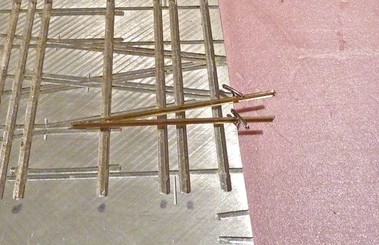
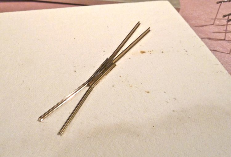
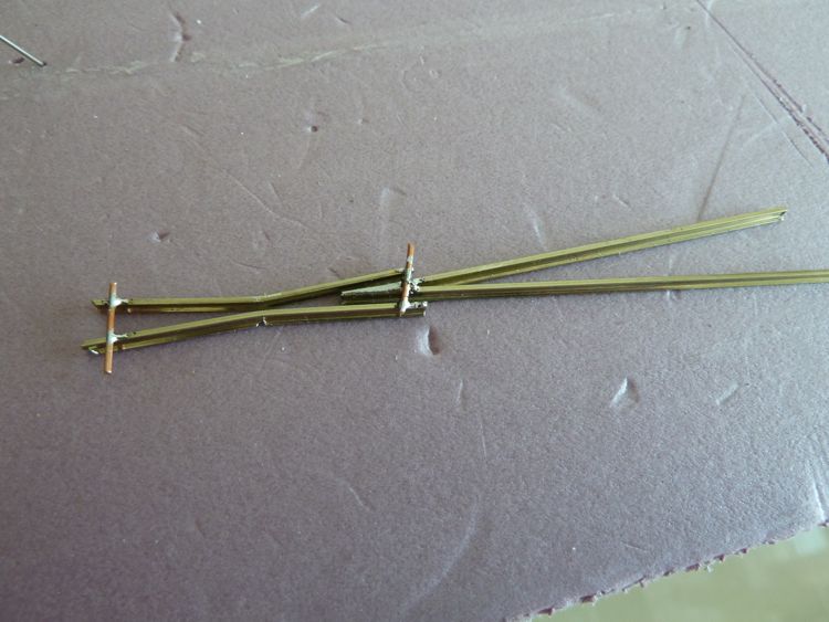
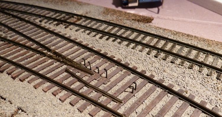
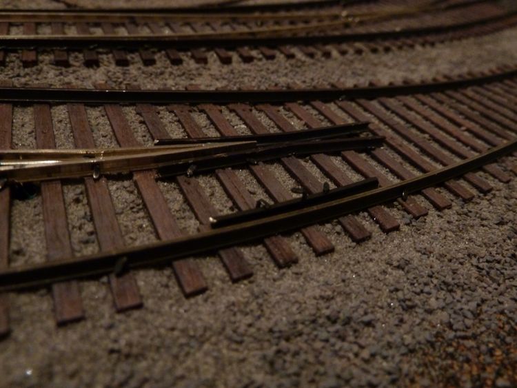
Before I go into the fix, I do want to point out one fixed problem — the curve of the points. in the picture below, the point on the left is one I've re-curved — the one on the right is how it was when i pulled it out of the layout.
So curving that helped.
Now, back to the fix. The issue turned out to be me; specifically how I had spiked the outside rails near where the points meet them. The ME spikes are a bit over-sized, so the heads can push the rail more than you'd think — or at least more than I thought.
I pulled out all the spikes near that part of the rail and reset them. Now, the switch works slick, slick, slick, both my bare test truck, and my regular text boxcar. It's a good thing to watch for as I continue.
I was so excited to find the problem, instead of starting another switch, I ran trains instead!
Slowly working on the next turnout....in this case the wing rails for the frog.
One thing I've found to make this a bit easier, is to "pre-spike" the pre-drilled holes that come on the Twist Ties.
I than anchor the ends tight, but leave the middle row until I get the other side in place.
Once it is, and that is spiked down on the ends, gauge is checked, as well as the rail placement. This shot shows how the Twist Ties have rail border guidelines etched in.
And once all spikes are down, I'm now checking the gauging at many, many intervals..
A tough lesson for me to learn, but a good one!
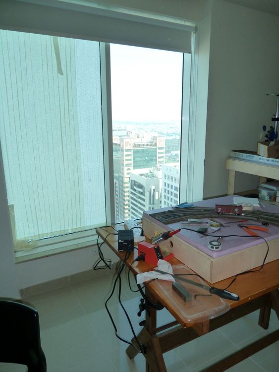
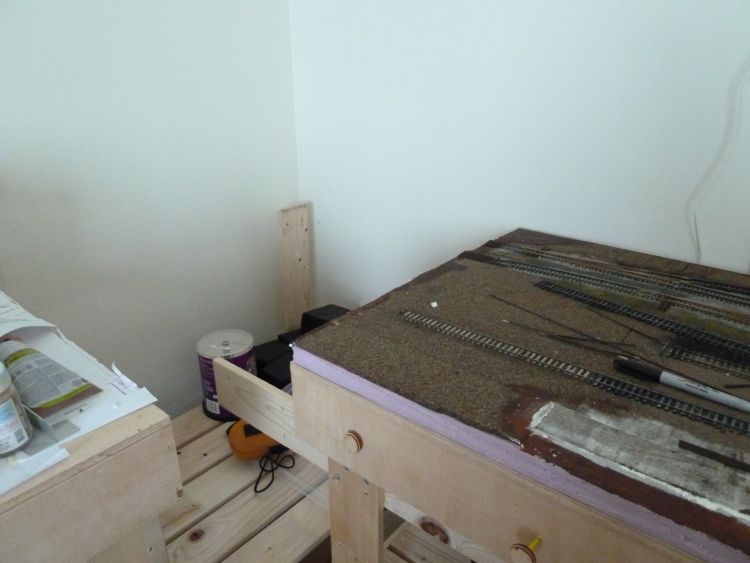
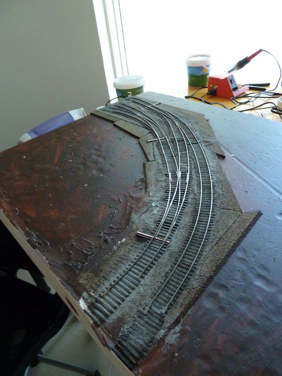
The room where the layout is suffered a broken window, and being on the 22nd floor, the replacement glass was long in coming. I was so irritated by the fact I hadn't' been able to build that I finally had enough. I dug through my stored things, and pulled out enough to get back to work on this module.
One of the advantages of building in this way (in a modular fashion), is the ability to do just this (the broken window is the one to the left)
Progress on the next turnout was good. I got this point in
And than the other, and voila, it was finished.
This one went much easier and faster; i was able to spend some time tweaking and spiking until cars ran across it nicely.
So just one more to do, I've left my stuff out, if they do come with the glass, well, they'll just have to wait!
We're still waiting on the window, but the track work is complete!
Working on the last turnout, I finally realized that I could use pre-weathered rail. Doh!
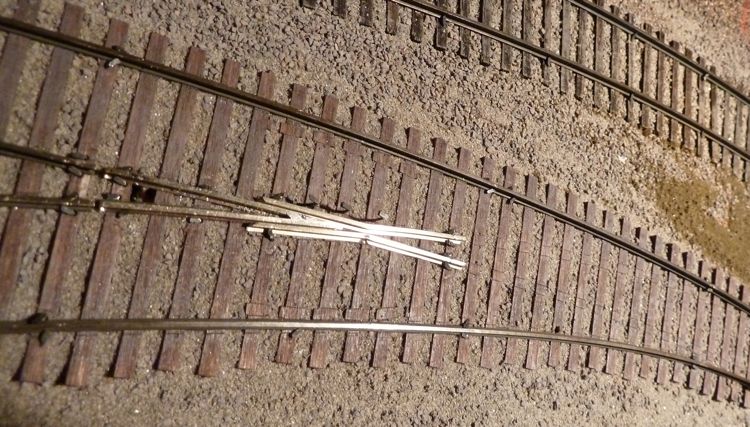
It's hard to see in this picture, but I've discovered that you can add a spike in between the rails and guardrails, as long as they are turned with the head parallel to the rail. This creates an almost perfect gap with the ME spikes, and really anchors in both the guard rail and the running iron. The middle spike is the in between one.
And finally, it's done, spiked soldered, and tested. Cars even seem to run through it!
It took a lot of time to put these three turnouts in. I'm not displeased with my efforts, but with this experience behind me, I know the next ones are going to be a lot, lot better.
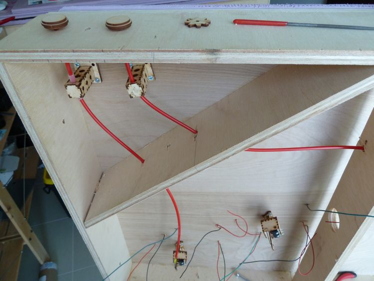
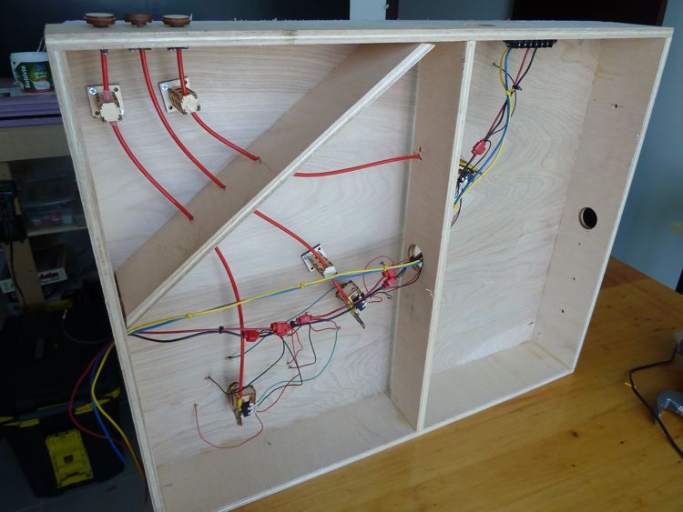
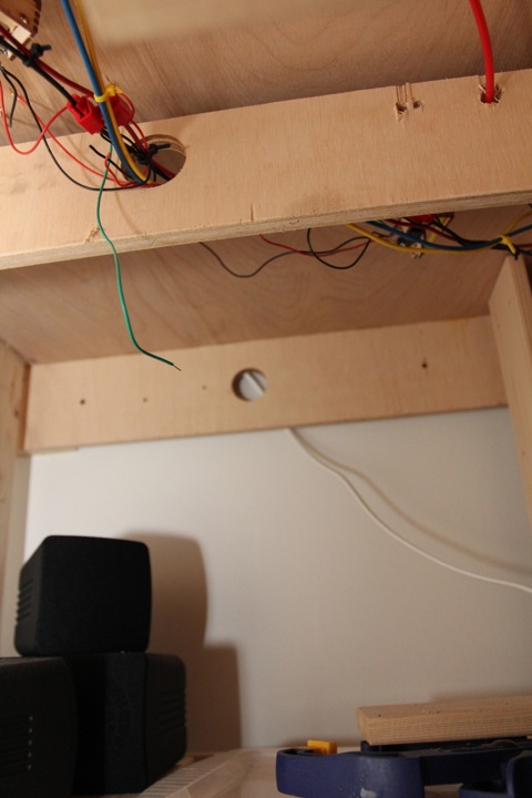
And with that done, it's time to work underneath.....
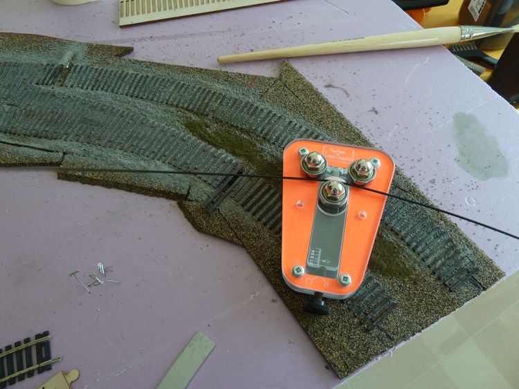
I have to say, the more I use the Fast Tracks Bullfrogs, the more I like them. But I digress, I had a good 5 hours today to work on the module, and I was able to knock it out!
First task was assembling some 'frogs. The two on the left are the newer ball and spring version, the one on the far right (with the smiley face) is one of the first generation magnet ones.
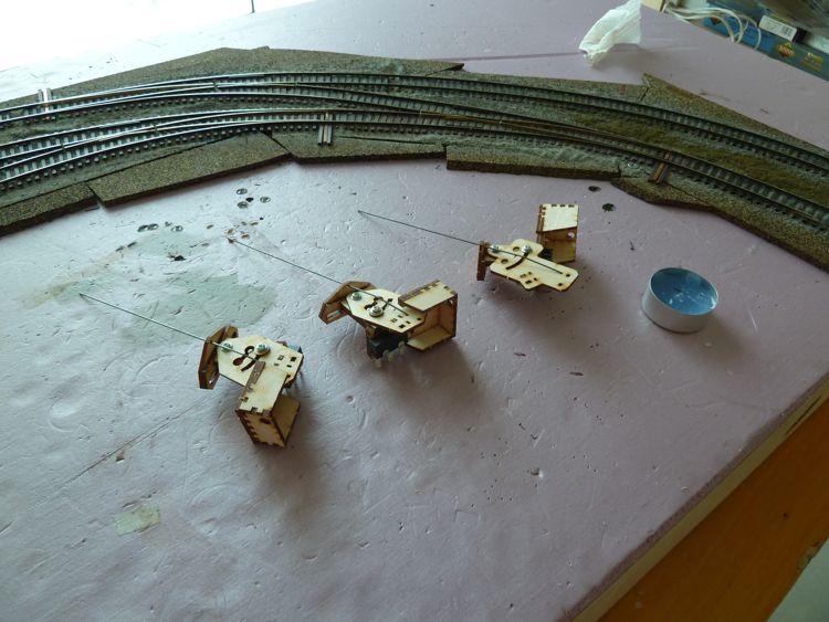
I have to admit I was not pleased they changed the bullfrogs at first, but now I'm a believer. The new ones snap nicely into place, and have a sliding mount screw hole that improves alignment (and makes an easy installation even easier).
This was my first installation on a curve (previously everything had been perpendicular to the layout face), and it took me a bit to get the first into proper alignment.
The others, though, went in quick.
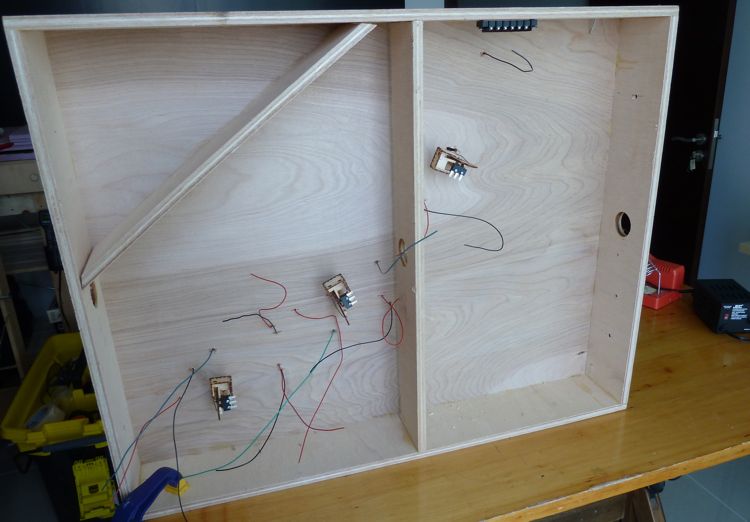
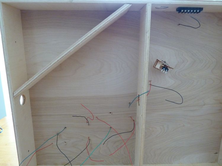
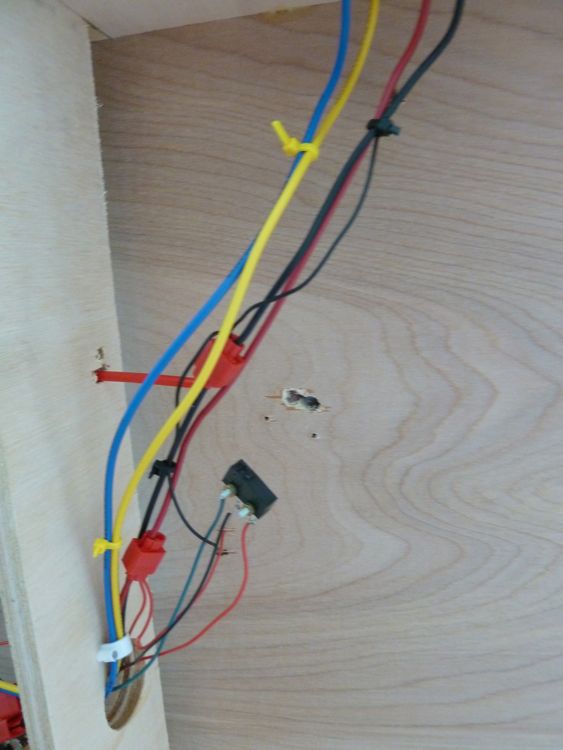
(You'll notice I'm waiting on the wiring until the bullfrogs and control rods are in place, I thought it would be neater).
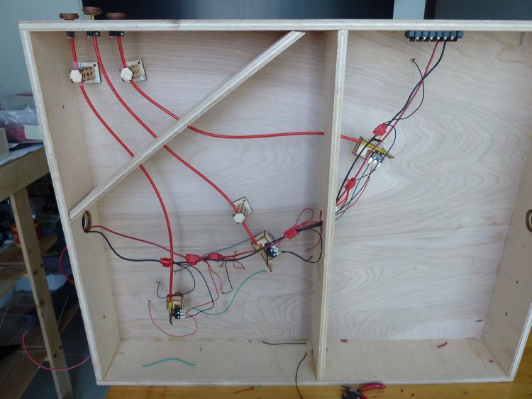
Starting right to left, I ran the first control rod. I was thinking of removing the angled cross piece, but than decided to keep it instead and simply drill through it.
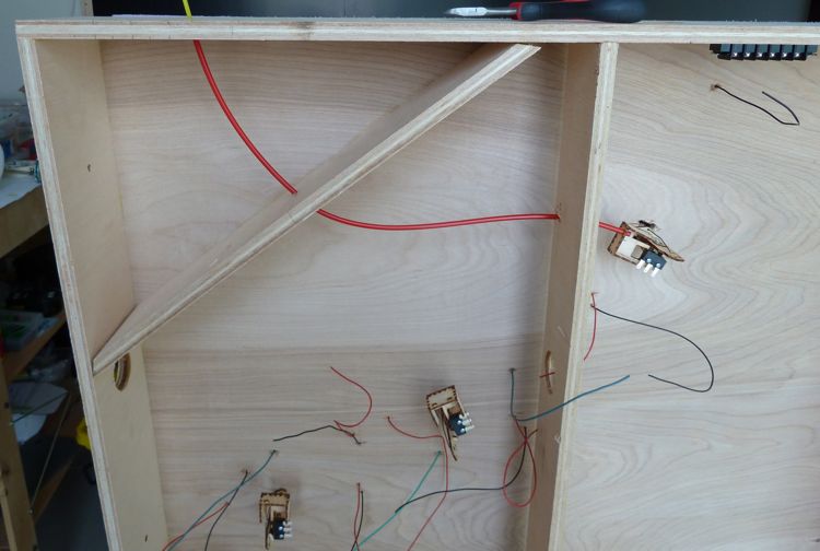
This path resulted in the red sleeve being right at it's maximum limit to the fascia. Not a big deal, but as the yellow control rod is exactly the same size, this does lead to a problem. I used one of the connecting rods from Fast Track's turnout support units, to give myself the extra length needed for full control rod travel.
I still wasn't happy with the curve at the fascia end, so I removed everything, and installed one of the support units to pull the curve into a happier place. I know they look like kind of sharp curves, but it's amazing how smooth it still operates.
Next up was the far left, no idea why I skipped the middle, but I did. Learning from the first, I went ahead and installed another support post; this is also needed as the 18 inch rods don't make it all they way to back of the 24 inch module. Two sleeves, and two rods are joined in this run.
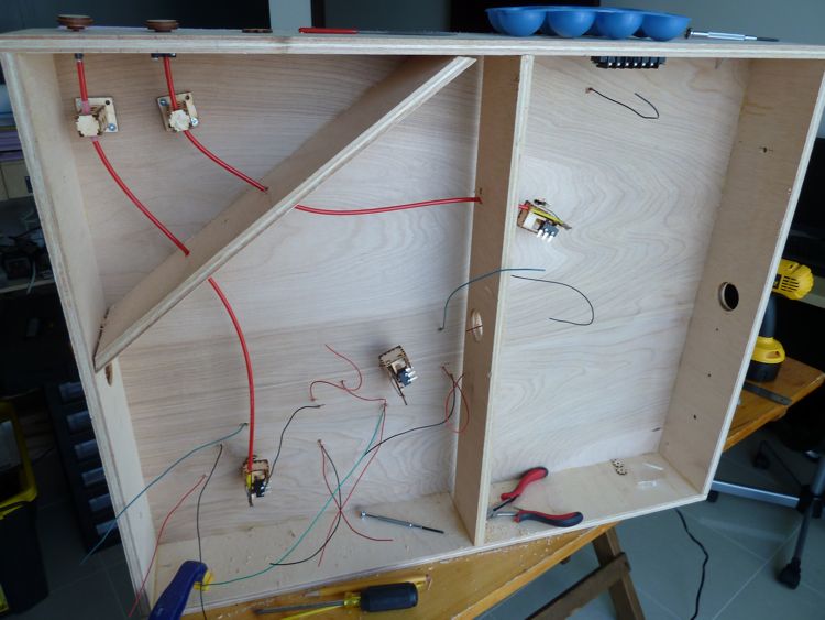
And than, the middle one. You'll note that I put the support towards the bullfrog on this one, I did this to ensure the control rod pull was straight going into the bullfrog itself and didn't twist.
You may also notice that all of the pulls are tight to one side of the module, remember this is a corner unit, and only a few inches of the front fascia are visible.
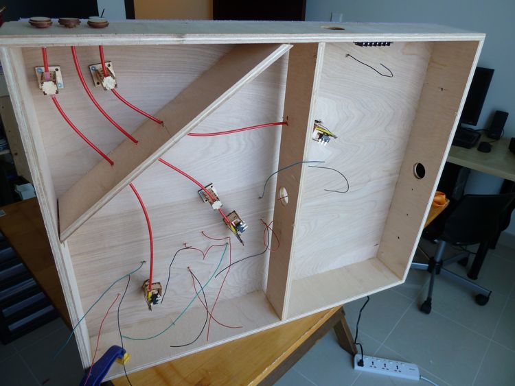
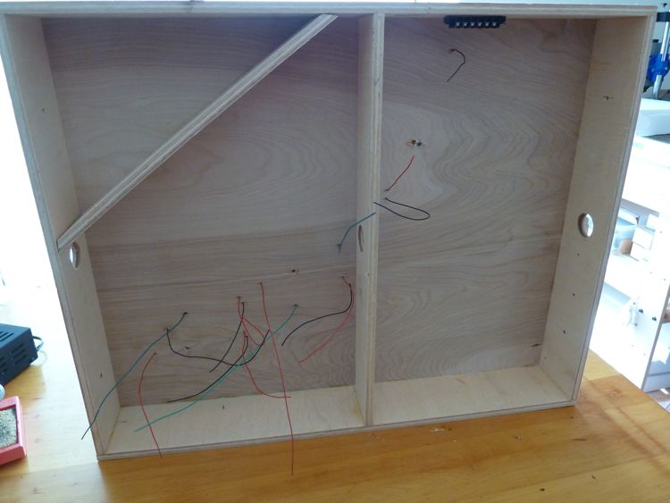
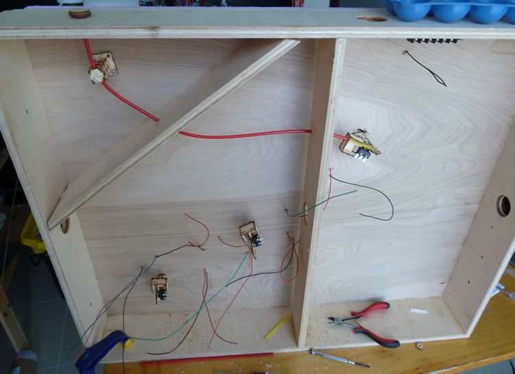
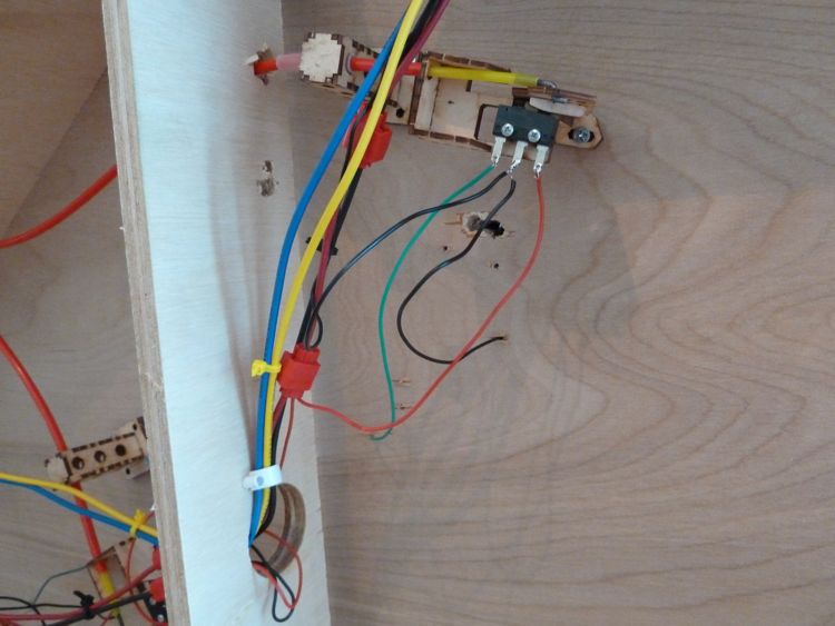
With the controls done and working, it was time to wire it up.
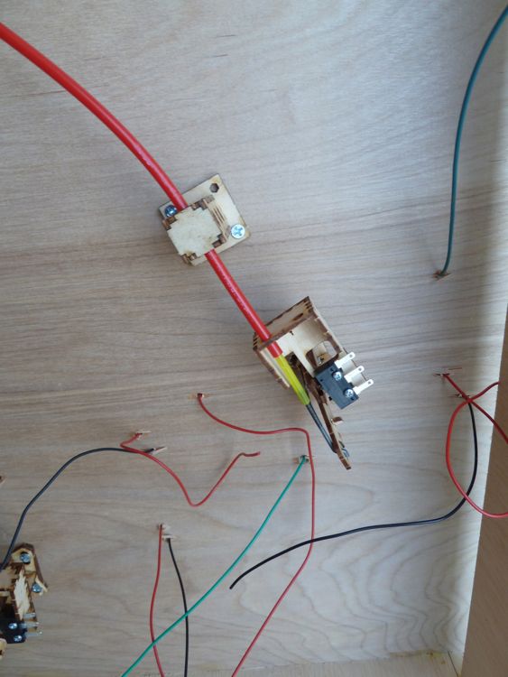
First, I ran the track bus from the connection strip out, and tagged in some feeders with suitcase connectors.
I than soldered up the bullfrog connections, only to realize with testing that I had mistakenly swapped out the wires for the switch. Another half an hour to remove all the wires, and re-attach them in their right place.
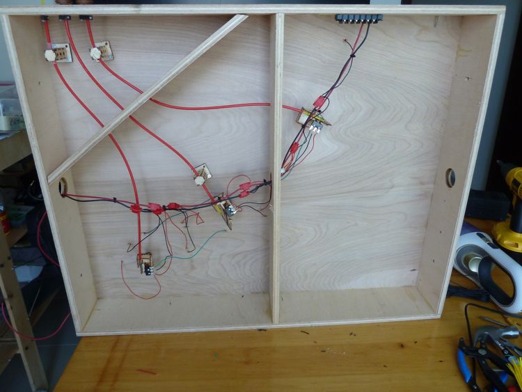
With the track bus wired, tested, and tied up, I ran the accessory bus. This was perfunctory, as there is nothing on this module that needs a feed.
so she's ready to connect.....now if only they'd hurry up and replace my window!
The install time for these can vary from turnout to turnout, but as a rough estimate
- 15 minutes to assemble
- Time for glue to dry (I try to wait at least a day, so I'll often make these in advance)
- 10 minutes to mount and align
- 20 minutes to run control rod (this is the hardest one to estimate, a simple one goes in quick (5 min), the first couple on this module were more like 30 as I wasn't happy, and kept re-doing the job.
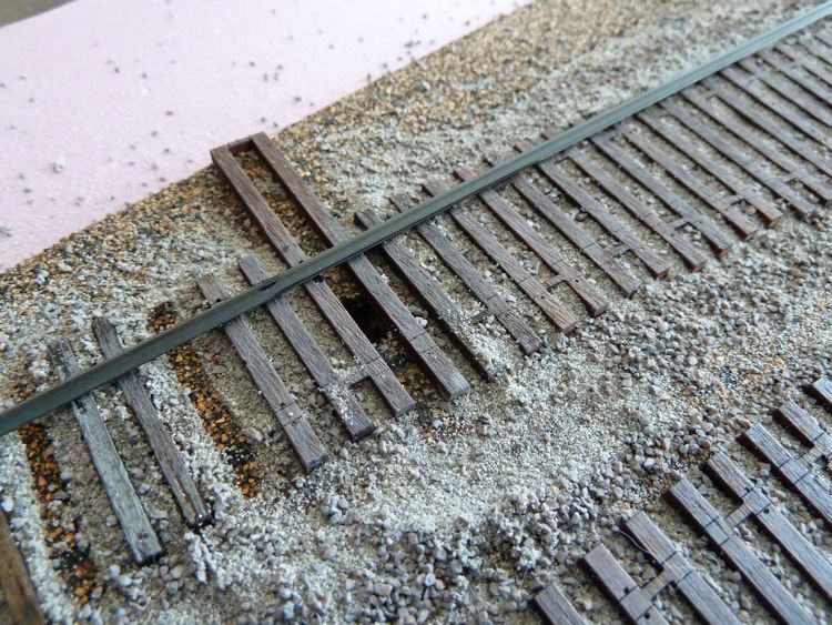
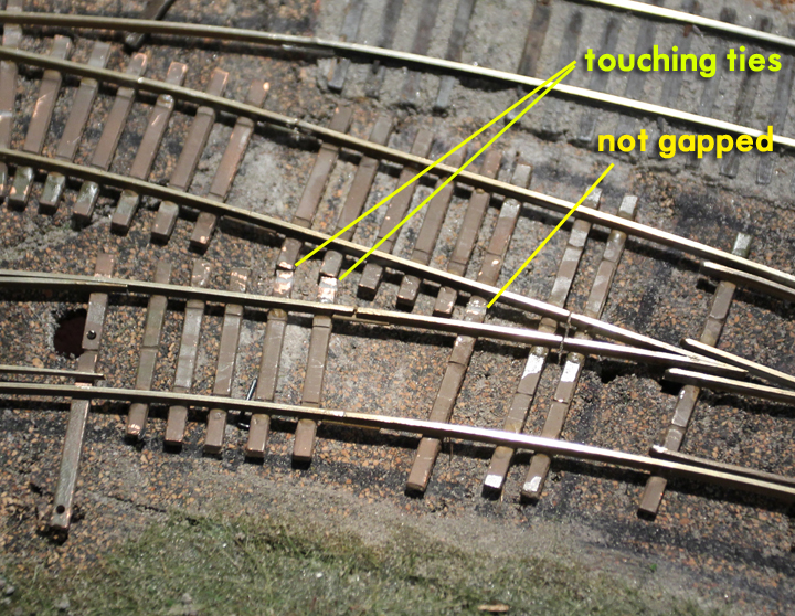
- the outsides of two ties on opposite rails were touching
- another long turnout tie that I put in wasn't gapped in the middle
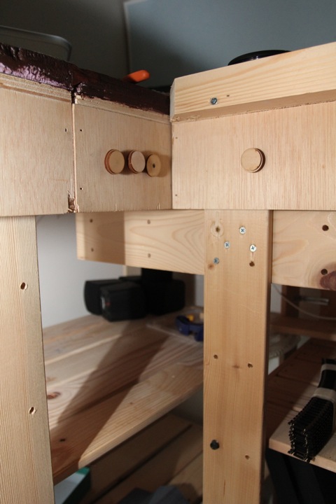
- Module base construction - by design, everything sits within the module base (for future transport) making access in this case a bigger challenge.
- Shelving as a base. The shelves are great for storage, but hinder access. They are removable, but are integral for the structure. Removing the top shelf is a possibility, but I don't think the bottom shelf can support my weight, and I would end up doing more damage than fixing things.
I haven't used a tortoise, so I'd have to imagine that the only time with those is the installation and alignment; wires are a lot easier to run than a stiff(er) control rod. I did try bluepoints a long time ago, before the bullfrogs came out, and I hated them. They were a pain to get into place, the throw wasn't sufficient to throw my turnouts, and I still had to figure out a control. The Bullfrogs are a great price, and work well.
Modular construction has it's advantages (as you've seen). But it's not the right solution for everyone, everywhere. For my situation, it's worked out very well, and yes, I enjoy the ability to work on the bottom side without staring up. I'm also hoping to move these the next time I myself move, and I'm also confident that the under work will survive that trial, as it's fully enclosed by the ribs and sides.
Back to this one, I plugged it in. You can see here why the control rods are all crammed up to the one side.
And at first, the alignment looked good.
But naturally, something shifted, somewhere, somehow.
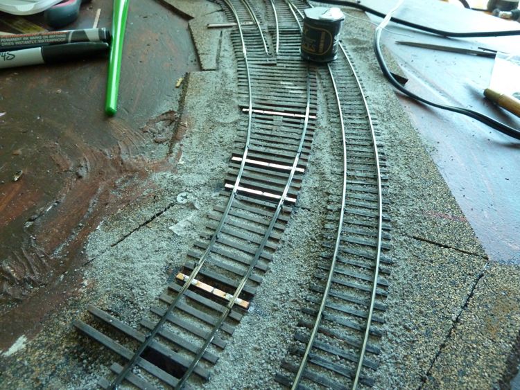
In order to smooth out the curve, I removed these ties
I chose not to tear out the entire curve, and instead put down some new ones that would line up correctly.
I know, this looks bad, but bear with me!
Back in place and with the modified curve in place, I filled in the gap between them (I used putty here, as there was a step down from the cork pad to the foam on the module I wanted to slope).
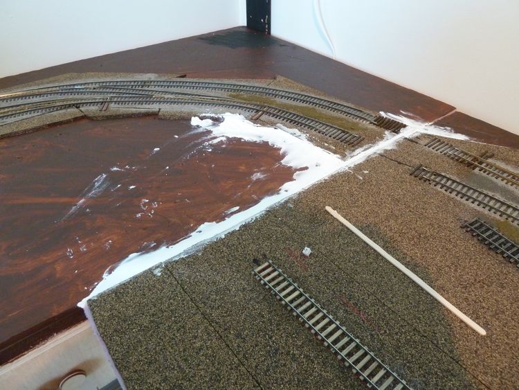
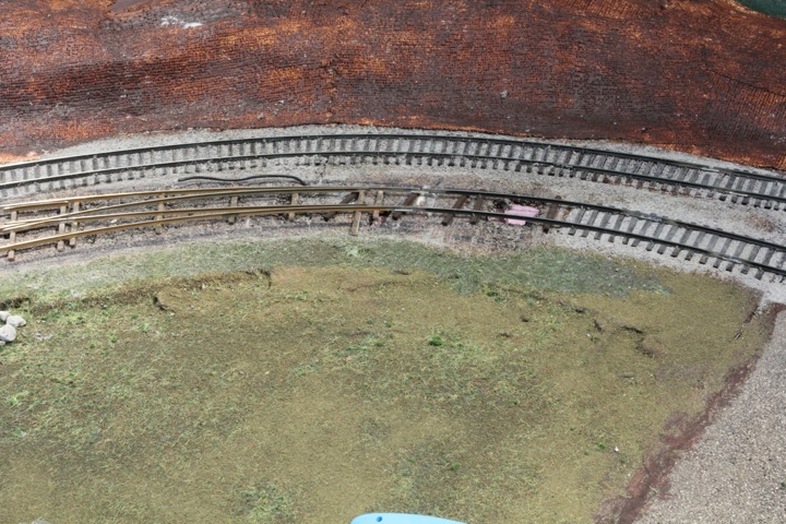
Crazy, huh? Check out the curve once it was all in place. (the top one - the bottom one isn't set yet).
So that was ok....than I ran into a decision point I hadn't planned for, expected, or wanted.
The rail curve seems to work in practice - again, I've run trains across it, even passenger equipment, and I don't see any issues.
The tie path is not ideal. Other than ripping a lot out, there is no way to fix that other than to disguise it with scenery, which I'm planning on. But the rails seem to work.
A Second Try
So.....there was something in this spot...
But I ripped it out, because the turnout that was in there, wasn't up to snuff.
It was in gauge, the empty truck runs through it fine, and even a freight car passes without issue.
My locomotive, though, is a different issue. It derailed every time when the diverging route was thrown, and after a couple of hours of tweaking, measuring, spiking, soldering, I gave up, and disconnected the module.
I decided enough was enough - this is a critical turnout, as the track on it is not only my switch lead for the yard, but also the route to the branch line. I need this working flawlessly, and it was clear this wasn't going to cut it - so it gets cut out.
First step was removing the bullfrog.
Working from above, I pulled spikes and rail up, and removed the feeders (they were pushed below).
And than started scraping away the ties and ballast.
It didn't take too much time to get it to this stage...much faster than to put in!
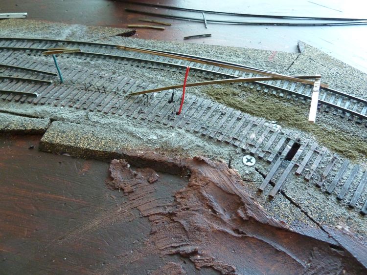
I than drew the new outside radius (tie edge) from a marker I put on the module prior to it's removal. I will be able to get a smoother curve by reworking this, and the last bit of track on the other module as well.
Then I pulled out the turnout ties.
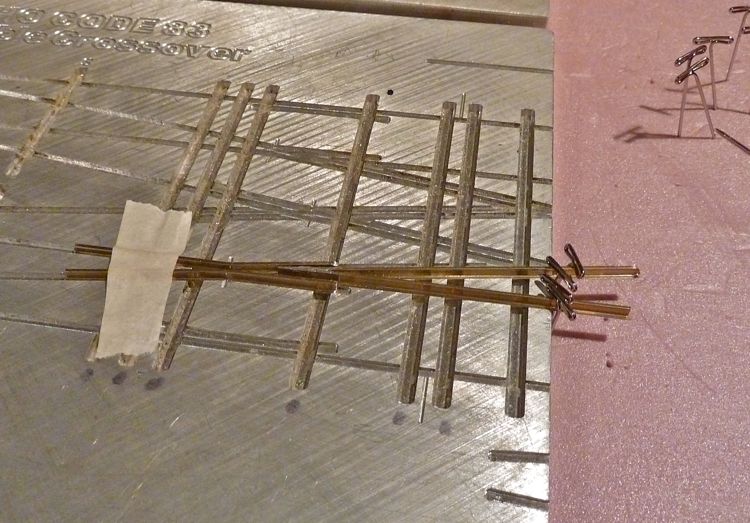
Having a good set of entrance and exit points, I was able to slide the turnout around until I got the best location I could find.
Marked, and throw bar hole cut. the masking tape is covering the holes from the previous layout (feeders and throw bar)
Glue...
And the ties down for the count.
So I let this set up, and hope for better results this time!
I agree with the old morale "If a jobs worth doing, then do it right the first time". I also agree with the other statement, "Experience is the best teacher".
I think now I understand some of the trickeries of curved turnouts! To the Gentle Reader who may be thinking of trying any of this, do one on it's own as a test before jumping straight in.
The next ones I'll do, I am going to print out the Fast Tracks templates from their jigs, and use that as a curvature model, much as I did for the straight turnouts on module 2.
Ok, so on to bulletproofing (or so I hope).
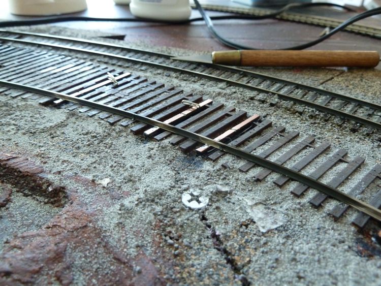
I got all of the ties down and in place. I thought I can help resolve some issues with this turnout as far as wiring, gauge, and rail creep goes, and replace some of the twist-ties with copper PC ties that I can solder to. Here, I've marked out the few I'll replace with a Sharpie.
They were cut out.
Next a few PC ties were put in place and measured for length.
Then the ties were stained
Finally the cut PC ties put in place (there is a slight shim under each one to match the height of the wood ties; it should be buried by the ballast.
Next up is to weather these ties, ballast, and begin laying rail back down. I'll spare folks those intermediary steps, and skip right to the rail work in a few days time.
After the ballast went in and dried, it was time to lay some rail. This stock rail was first; note that I burnished off the weathering where the PC ties will be.
I held the PC ties in place with these pins while soldering. Note that I sharpie the outside edges of the tie before putting them down; makes them easier to paint later.
Then the other stock rail. My process was to spike these rails in place first using the pre-drilled holes on the Twist Ties, and than solder them to the PC ties.
And the Frog was next. Note that on this one, the entire frog is powered thanks to the PC tie; I think I'll be doing this for all future turnouts as well.
Finished. Again, thanks to the PC ties, I didn't have to run additional feeds to the points, so this is another big advantage.
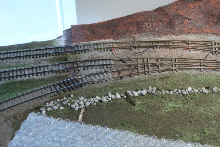
Another look. You were right, there is a slight straight section, but I hope it won't be too much of an issue. The outside curve is nice and smooth, and the test truck rolls right through without a bump.
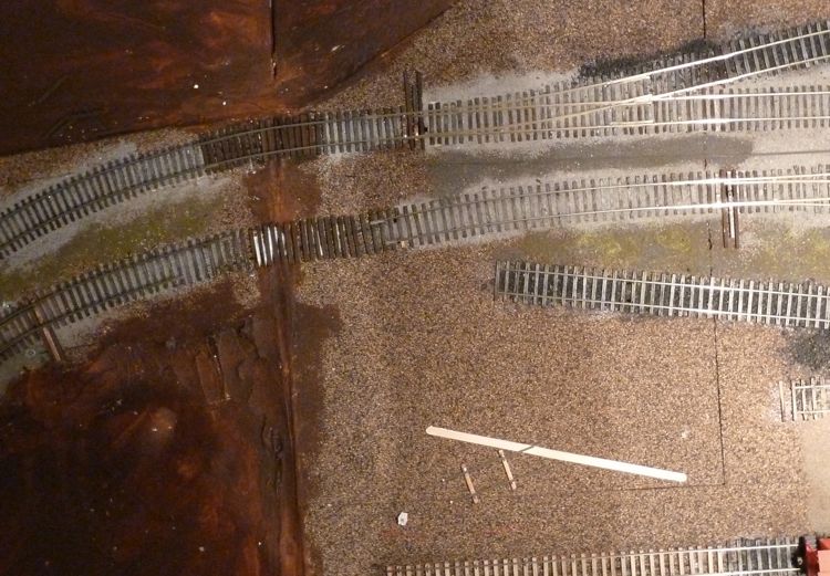
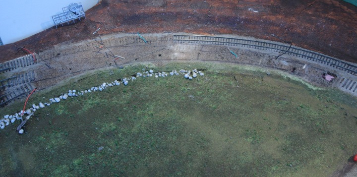
Overhead view.
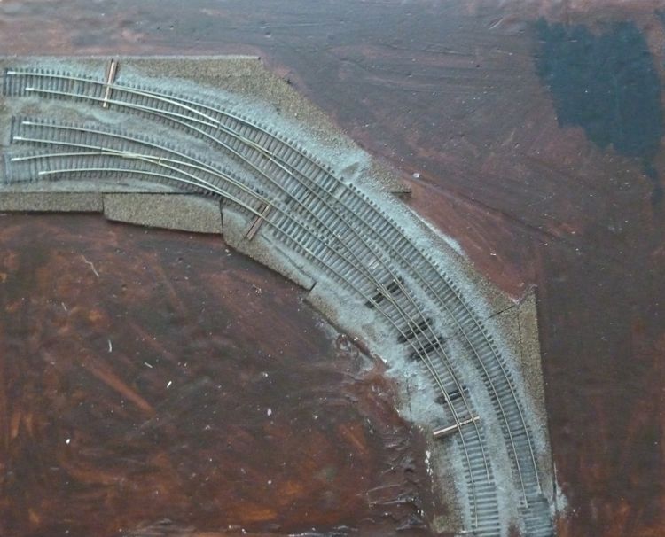
From underneath....You can see the old position clearly in this picture.
Just so folks are aware, this re-do process cost me at least four hours of labor. I tell you honestly, it makes the price of a manufactured turnout, or a jig, a lot less prohibitive. I do enjoy the process, but it was a bit frustrating to have to go back and re-do something that I messed up.
So after all the electrical tested out, it was time to put it back in place.
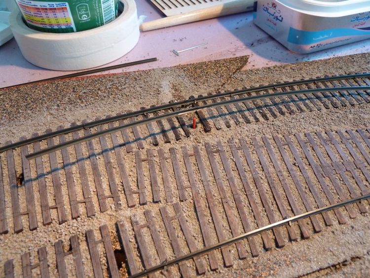
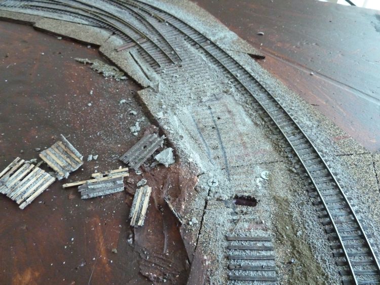
You can see how the ties line up; the new path is much better, but entails ripping out a fair portion of rail on the other module (the black line indicates the new tie path). Yeah, ripped up some cork by accident.
After filling the gap (and hole), out came the soldering iron and pliers, and I ripped out the entire length of rail back to the switch.
and than got to work removing the ties. Razor blade and spachula for the win!
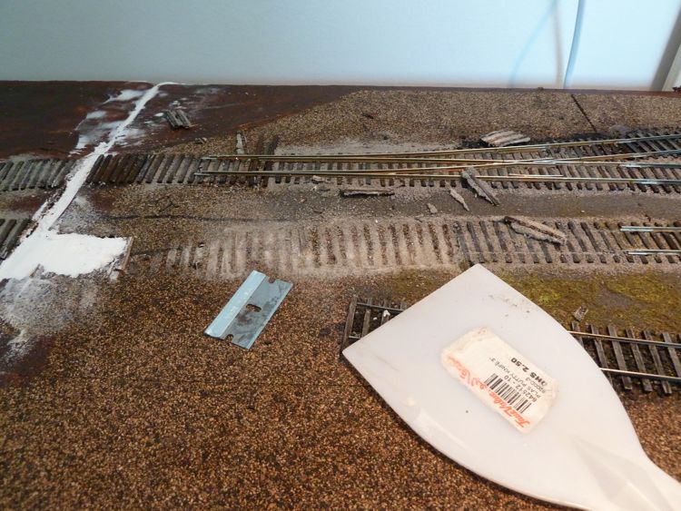
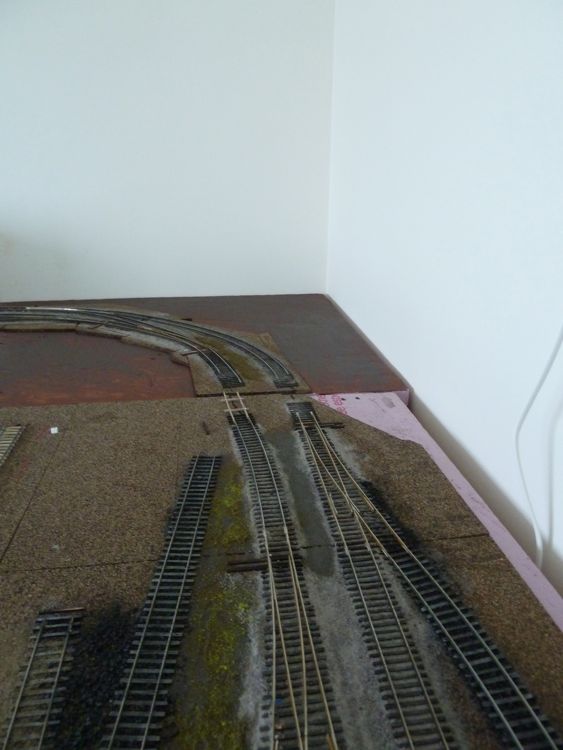
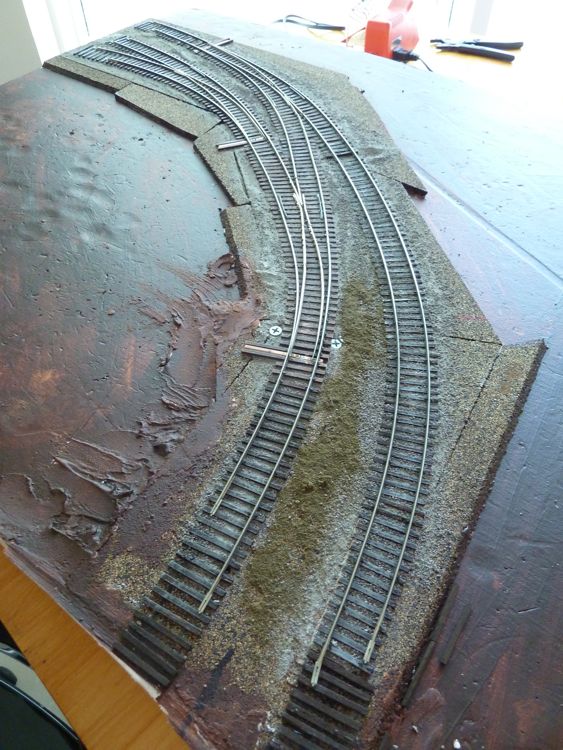
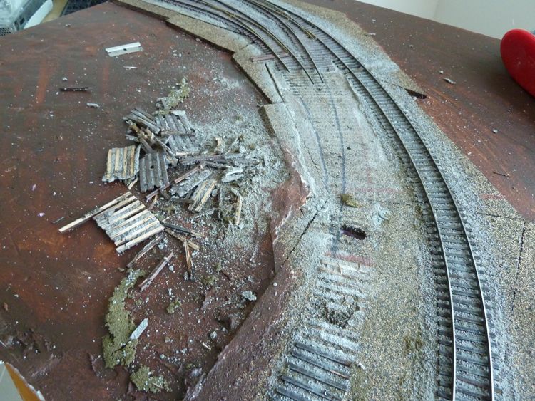
Here is an over head shot after cleaning up the area. You can see the new path will be much, much better. I may redo some of those ties on the other track as well.
I finished off the ties, weather, ballast, and got rail down to connect this module (once again) to the second. The rail flow is much, much better as you can see.
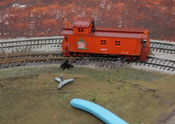
Once the wires were connected, it was time to give it a whirl.
My test truck, rolled though at high speed, though all the straight and diverging routes. A single box car did the same. I pulled out my S2, and firing up the DCC, ran it as well through all the routes. Success!
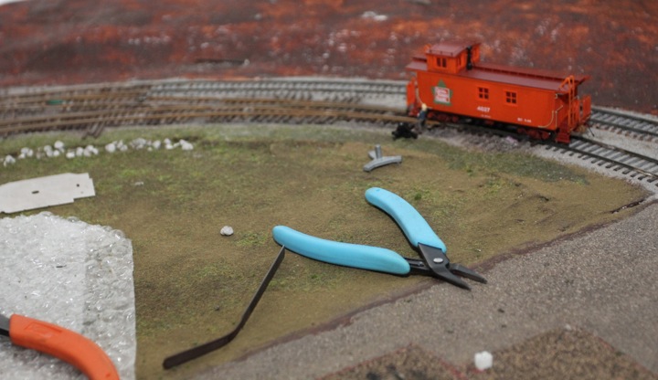
So after working a little bit on the next module, I ran a small operating session, really nothing more than breaking down a train into the yard. Things were going swimmingly, I was able to pull a long string through the straight route of the new turnout without issue. I decided to do the same through the diverging route, and that's when the tears began to flow.
Pulling multiple cars through the diverging route caused an immediate derailment. After the first tears and colorful language passed, I considered ripping the whole thing out again, and starting from nil, including purchasing a curved turnout jig from Fast Tracks.
Fortunately, a wiser head prevailed, and after a cold adult malt beverage, I took a closer look at the offending spot.
Ah Ha! I had forgotten to spike just ahead of one of the PC ties, and the forces from multiple cars would push the rails apart just enough to derail around the tight bend of the diverging route, which explained why none of the single car tests showed the defect.
A few spikes, and voila, it was fully operational. There will be speed limit in this area for sure, but it's working well.
Once that is in place (module 4 as a whole), I can begin to really see how it will feel to bring a train in, break it down, and push it out again. In part this is why I'm trying to get module 4 done in a hurry to at least an operational standpoint, after that, I am thinking of holding off on the last three modules and instead turning my attention to scenery and buildings.
Third Swing of the Bat
Have I said yet that I hate this module?
I've laid the track out twice, and now months later, it's still not working to my satisfaction. I've tweaked, pulled, checked, spiked, re-spiked, filed, re-filed, ground, replaced, and it still sucks.
Which, of course, only leaves one option. Something I should have done months ago, when it would have been easier and less frustrating overall.
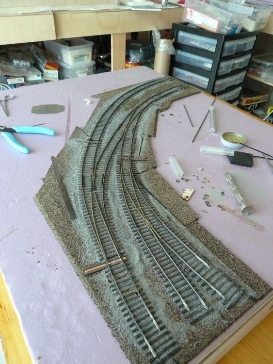
Full, and total replacement.
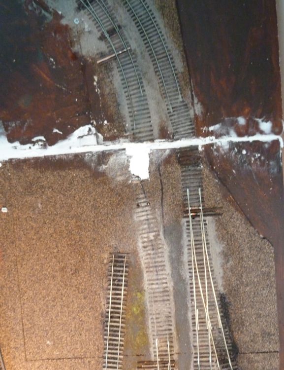
Here's the current layout.
After re-creation of the switches (based on the actual fast tracks template, which I should have done the first two time), the switches laid out over the current trackage. I was looking to try and meet entrance and exit points as close as I can.
It's hard to see in these pictures, the but the track geometry is much different - and I think it'ss the abnormal deviations in the current trackage that are causing me nothing but grief.
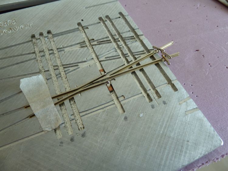
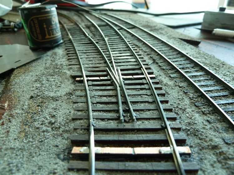
In order to not do this again, I continued to follow Tim Warris's (from Fast Tracks) example, and assembled all three turnouts into a single fixture, soldering in PC ties as needed. My hope is that this will guarantee the geometry and eliminate the derailments I was having.
and that's what I did.
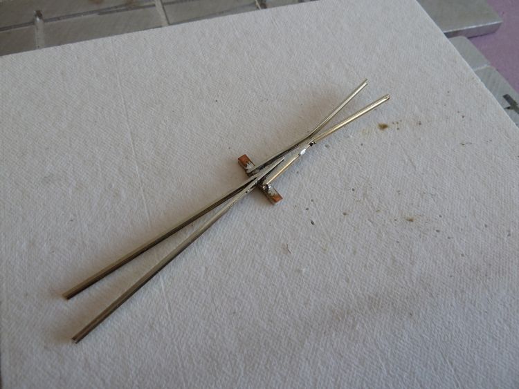
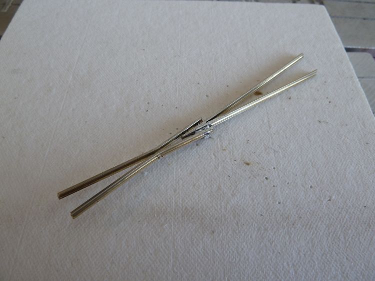
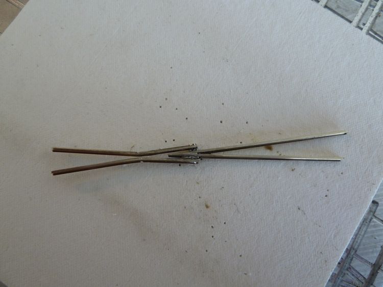
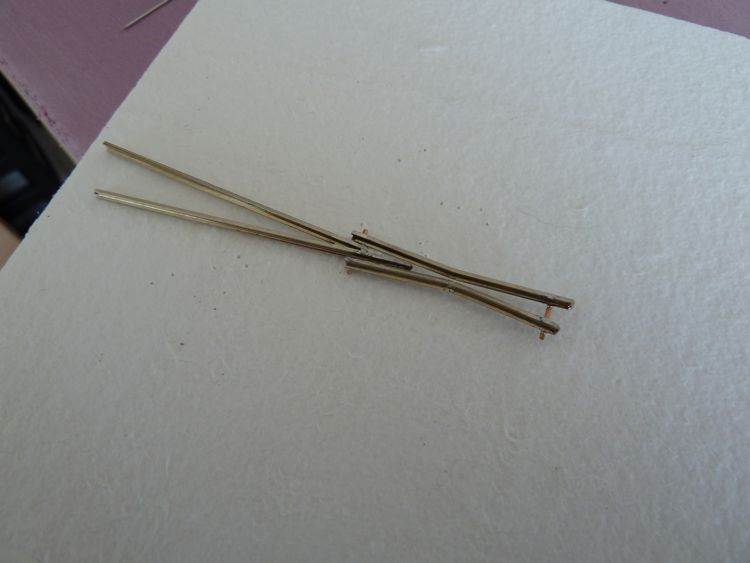
Here is the completed fixture.
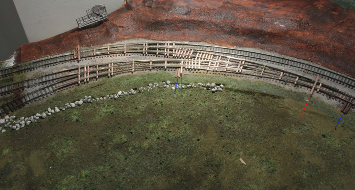
In order to try and demonstrate the difference in geometry, I marked the old throw bars in blue, and the new ones in red (the top left turnout will sit in the exact same spot, so it's not shown).
With the change in throw bar location, I will most likely not be able to use bullfrogs from below, and am instead going to use n scale caboose ground throws to control these two turnouts.
Have I mentioned I hate this module?
Up came the old rail, and it was removed (I was able to save a fair number of spikes). The ties and ballast came up easy — just sprayed on water, let it sit, and voila, up it came. An advantage of using just white glue, I guess.
Here is the cleaned up area - I left the feeder lines in place
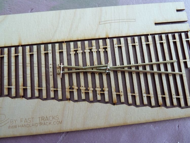
The first dry run of the new turnout fixtures

In the meantime, the fixture was checked for electrical isolation, and painted (great having a spray booth).
Now it was time to get it in place - I only put in a few ties to hold it, and run it for a while before finishing off the remaining ties and ballast.
Nothing was soldered in yet, but test cars ran across it with (mostly) success.
The lack of ties in areas, a fair amount of bounce, and the splice rail not being spiked into gauge yet is causing a bit of grief, sadly though it's already working better than the last iteration.
So now, of course, popped up a mystery short. A significant one, that I immediately blamed on the new track work (although I thought I was thorough checking them before installing. I pull the fixtures, and lo and behold the short remained.
Maybe, it was a stray piece of debris from my demolition across the tracks, or tools. I removed everything, including rolling stock, and vacuumed the track.
The multi-meter was now happy!
I reinstalled the fixture (still not soldered in for a reason) and the short continues.
I haven't had a short on the layout before, so I have to deduce that it must be showing up now as a direct result of the removal of the old track work. Was a wire or connection just a bit loose, and the work pushed it over the edge, or am I missing something simple?
The layout is a single block, so there are no short cuts by disconnecting the bus per module (as the rails are still hot on top).
After some effort, I found the short, it was in the new fixture, where I added PC ties in between two turnouts to create the whole shebang
I finally discovered this by removing the fixture again, and connecting one rail at a time until the shorts appeared.
Thankfully, it wasn't a systemic problem!
I missed these, as I checked the turnouts for frog isolation when they were separate - but must have forgotten to after they were assembled and soldered together (these ties went in as part of that process)!
For those interested, here is where the trouble started.
I should add, that so far my locomotive power tests have been successful — even my C Liner, which was not happy previously, sails through this now. Now to break out some steam.
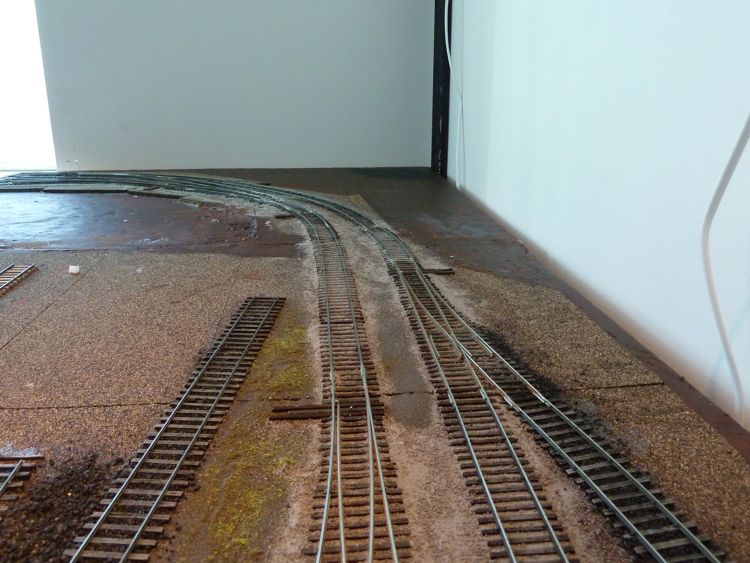
I now went to install the Caboose N scale ground throw on the one turnout that I was unable to reuse the Bullfrog. I would have preferred to have moved it, but the problem is access. Here's a shot from the front of the layout
Underneath (the abandoned Bullfrog is in the upper right behind that rib) - note that this picture is inside of the boards on the edge of the layout shown above.
It's just not a good place to work. This is compounded by a couple of factors
The best idea would be to remove the module, but I was reluctant to do that, by not doing so, I've unfortunately removed their advantage, and highlighted some issues with making a layout in this fashion.
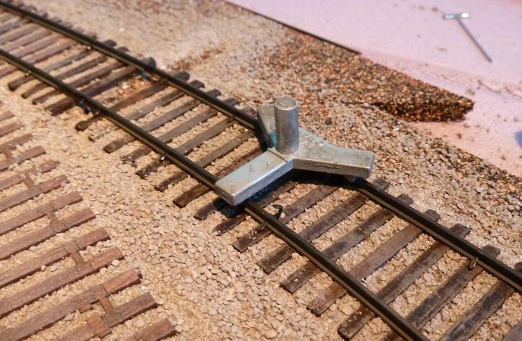
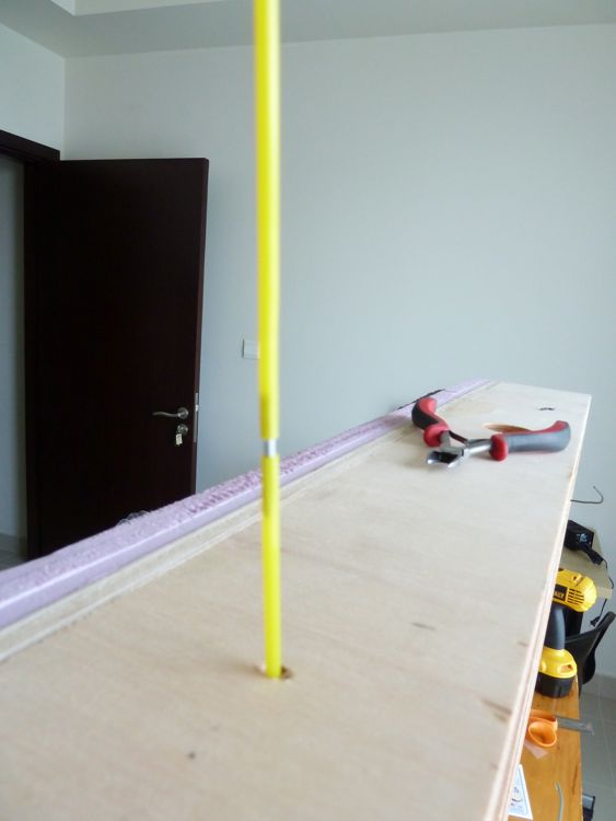
So the caboose industries N-scale throws become a option. Their a bit oversized, even in HO. Here's the promised picture
It is big, here is another one with an HO scale figure for size (I apologize in advance for this being out-of-focus, I just ran in this morning and took these without turning on the room lights)
So they are not great, but with some paint, they may disappear a bit more.
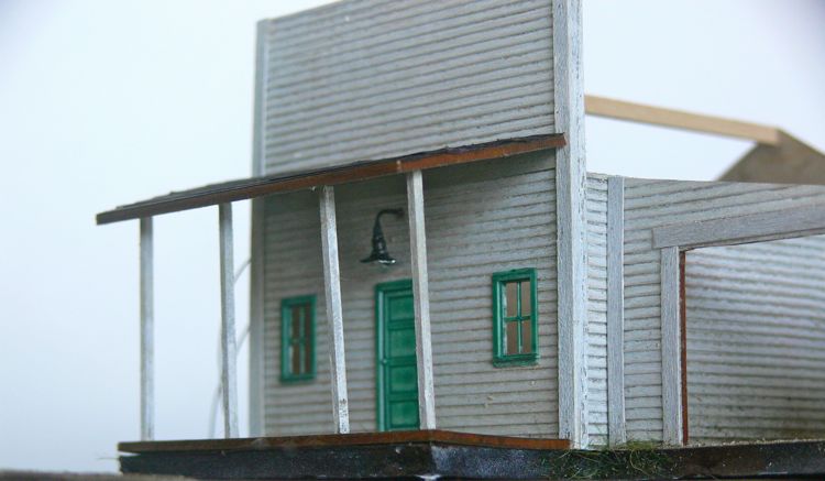
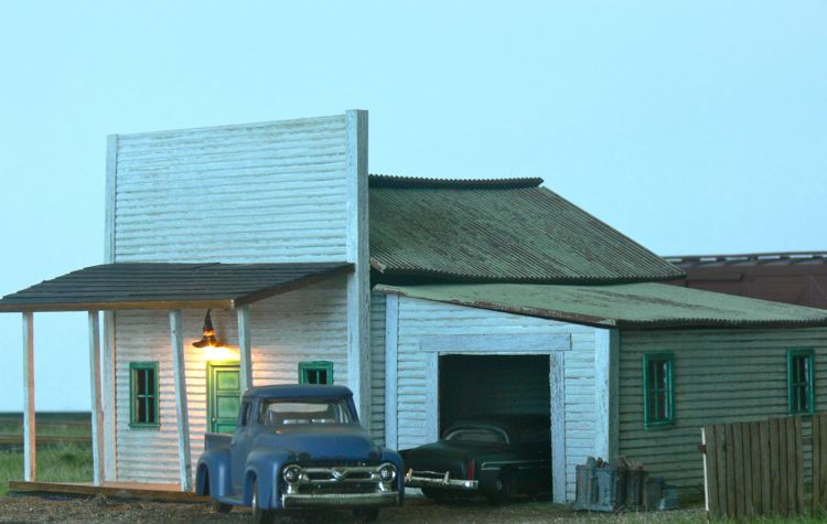
Scenery
One of the things I brought from home this summer was a bag of leaves. I kept them whole in my luggage, in case there were any questions on what they were, so this weekend I pulled out the food blender (when the wife was away), and ground the snot out of them.
I use these for a forest underlayment, as I just like the look better than anything you can purchase.
As a result, I was able to comeback to this corner and begin treating the wooded area on this module.
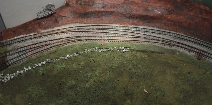
How it started/
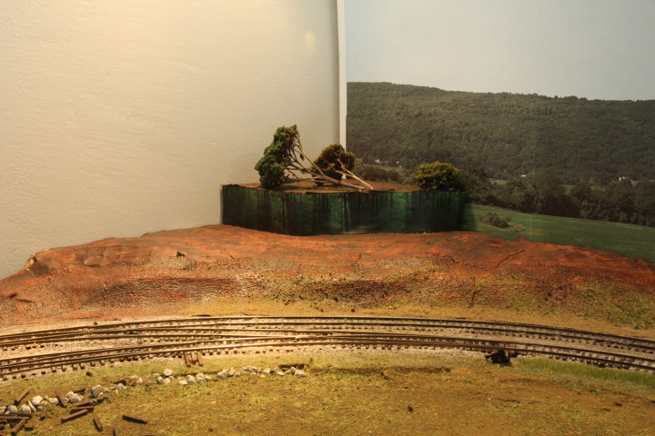
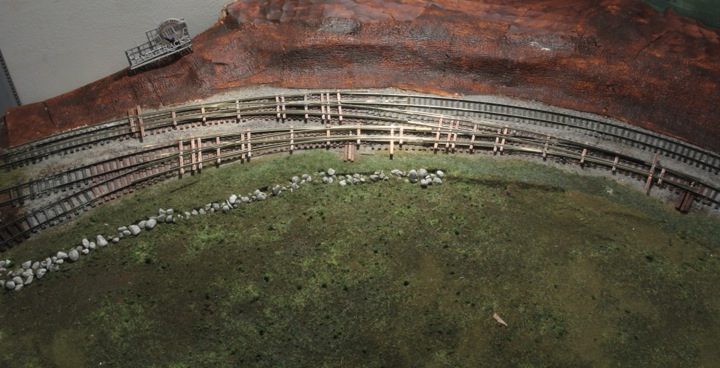
How it looked after the first coat of leaves/
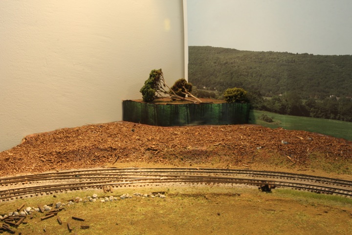
And in the end after a little foam.
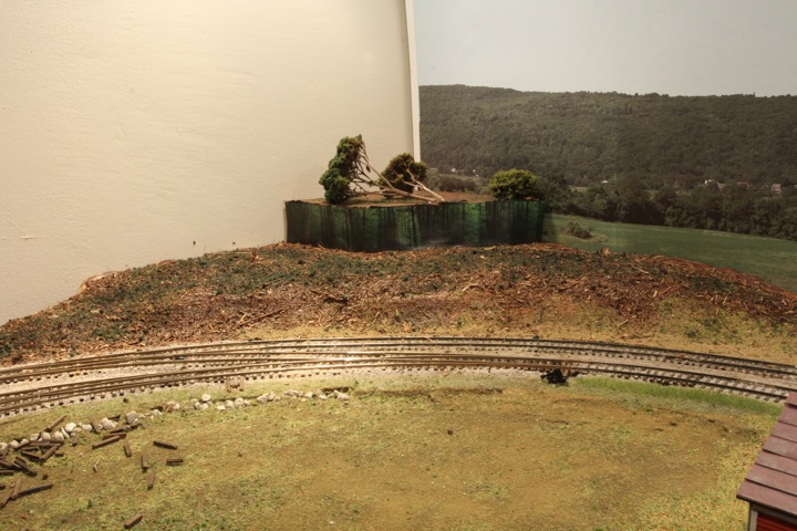
Now I need a better picture, and a slew of trees to get this corner filled in.