 Scarpia's MINIVerse - Model Railroading
Scarpia's MINIVerse - Model Railroading
Test Layout 2
Work in progress
 |
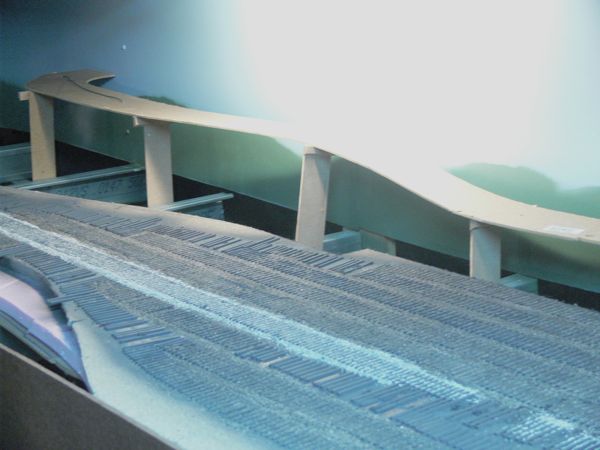
I picked up a piece of 1/4 inch hardboard for the background and fascia. Here is the background in place along the lower lever. The "cleats" you see are where I intend on attaching the cardboard strips. I'll paint above those. |
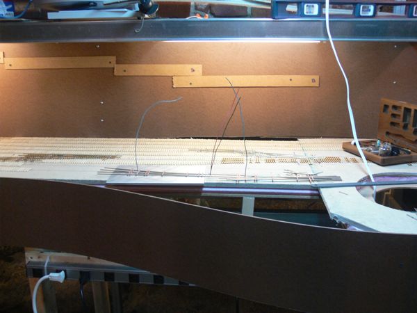 |
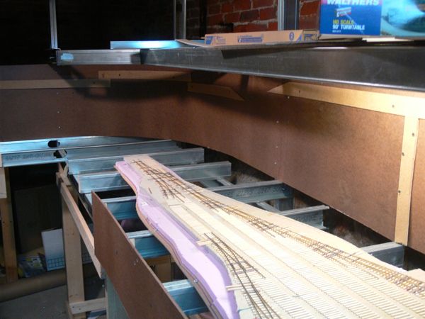
For the moment I've bent and curved the front fascia, however I realized that this might be a good place for my Easy DCC head unit, so I'm going to go back and square off the area instead. |
 |
|
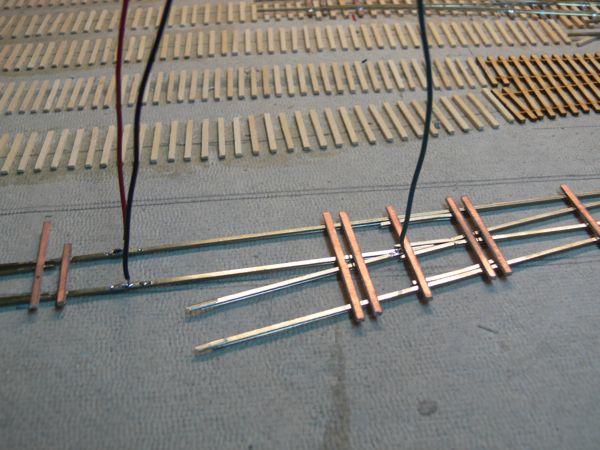 |
I've also started wiring the switches. First up was a feeder to each frog, and in this case, I soldered on rail connectors, and than feeder wires to these in turn. |
 |
Back to the background, I fired up the airbrush for the first time, and hit the areas above the "ridge" lines. |
 |
With a healthy bit of it done, and me out of paint, I went ahead and started with some cardboard strips. |
 |
Hot glue and a weave. One thing I realized is that I didn't leave as much room as I would have liked along the far track. |
 |
I resolved that in the next section by adding the large flat piece of cardboard first, and than the vertical strips. Here is the section covered in masking tape. |
 |
After some discussion on line, I ripped it all out. It was simply too steep, and too close to the edge of the track. With the cleats gone, I filled the screw holes, and primed the backdrop with PVA primer. |
 |
Once that was dry, I rolled a coat of Sky Blue from Behr. |
 |
The camera is not picking up the color for some reason, so here's a photoshop adjusted image. |
 |
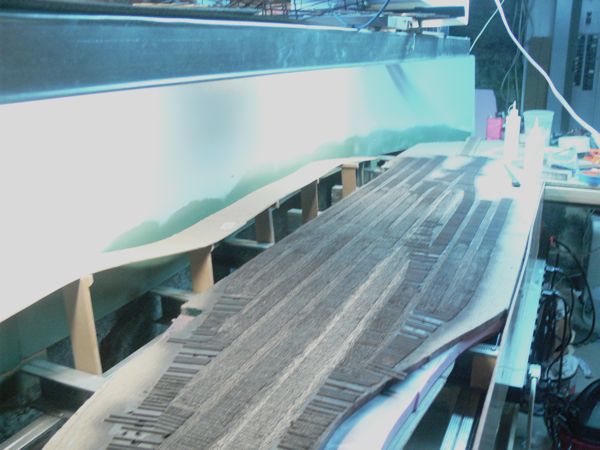
It needed another coat of blue, but before I did that, I tried a can of Sage green from Krylon and made a quick cardboard stencil for these hills. They reside well below the current scenery level. The risers you see are for the road along the back. |
 |
The road is made of MDF, and spliced in the middle section. |
 |
A series of fancy pants clamps hold the road to the risers for gluing. |
 |
|
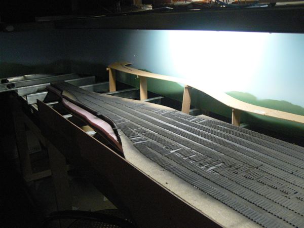 |
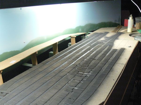
Next up was paint. All of the ties in place got a nice coat of weathered black. |
 |
|
 |
and than ballast. Cinders for the sidings, my gravel mix for the mainline. |
 |
|
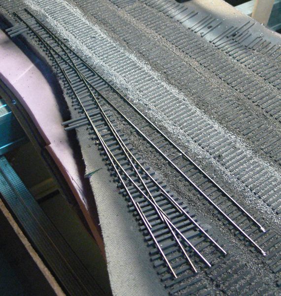 |
The first turnouts go in, complete with a blue point underneath each! I hand laid the bit of track you see coming off the top, and it checks out in perfect gauge. |
 |
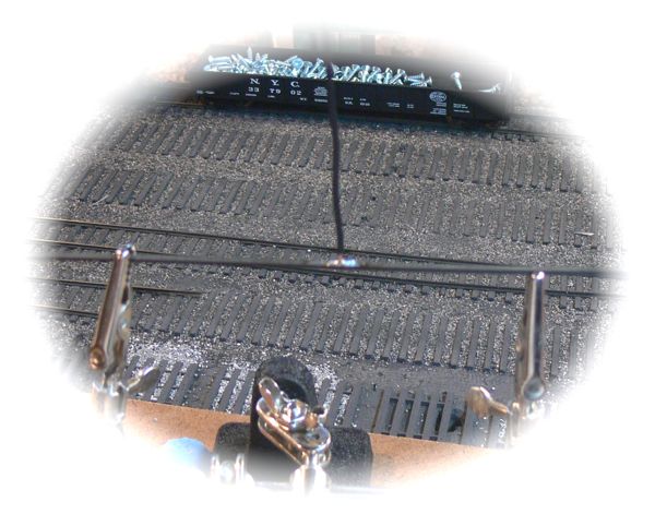
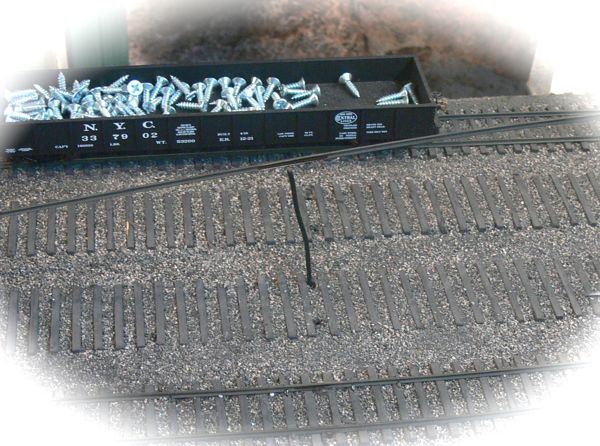
Track laying has begun in earnest, and here are the basic tools I'm using. I've found it better for me to spike both rails at the same time, I use the spacer block on the right to keep the rails in rough alignment on the ties, and the actual Micro Engineering gauge on the left to keep them in alignment while I spike. |
 |
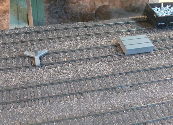
For power feeds, I've been soldering wire to the bottom of the rail. Here's a piece of rail upside down, after cleaning off the weathering to bare metal, the feeder is soldered into a vertical position. |
 |
and than fed down the pre-drilled holes. |
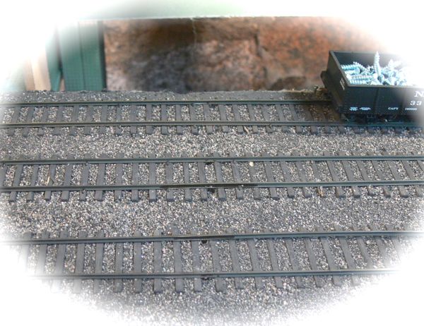 |
Once in place, it will be invisible with a touch of ballast. |
 |
and spiked in place. The heat from the soldering iron does alter the weathering on the rail, but I'll be going over everything with touch up paint later. |
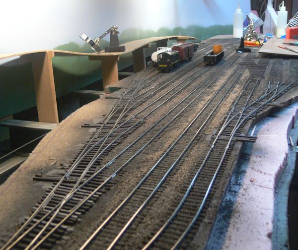 |
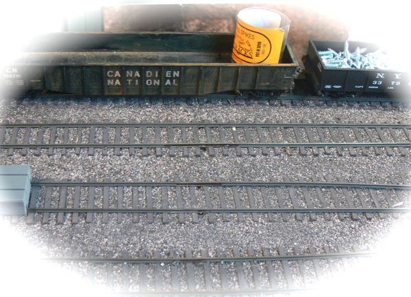
The yard so far. Yup, that's a locomotive, I have the feeders hooked up to the bus, and am running DC trains! |
'ere is dem nasty legal bits:
This website is completely unofficial and is in no way endorsed by anyone. All corporate and company names are used without permission. No challenge to their status is intended. ©2009. This site is the sole work of Scarpia (Thomas Garbelotti) unless otherwise noted. All content not created by Scarpia is copyrighted by the respective copyright holders.