Track Work
This will be my second "layout", currently designed to be nothing more than a test bed of techniques and methods. It is based on this simple but functional plan
With testing on the benchwork, roadbed, Fast Track turnouts and hand laid track behind me, it's now time to begin putting some of this into practice. I've already made a Code 83 No. 6 crossover and left hand turnout, which leaves me with the following still to push out of the Fast Tracks jigs for the yard area. Note that the plan just lists No. 5 Turnouts; as I got a No. 6 jig on eBay, I've converted the mainline turnouts to 6's.
| Code | No. 5 Left | No. 5 Right | No. 5 Crossover | No. 6 Left | No. 6 Right | No. 6 Cross Over |
|---|---|---|---|---|---|---|
| 70 | 2 | 4 | 1 | 1 | - | - |
| 83 | - | - | - | 2 | 2 | 1 |
With the list tallied, it was time to get to work.
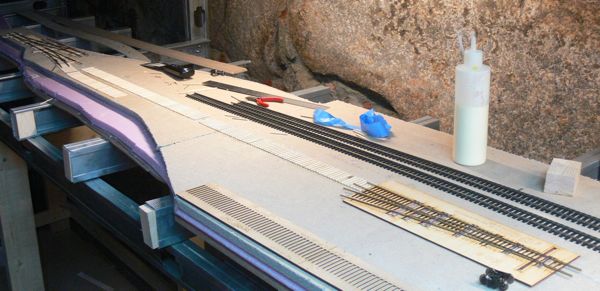
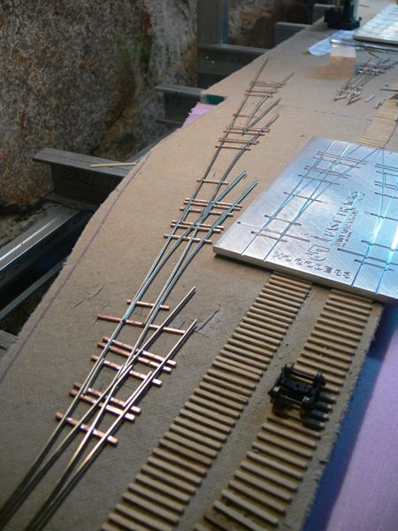
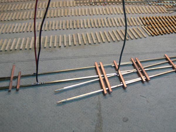
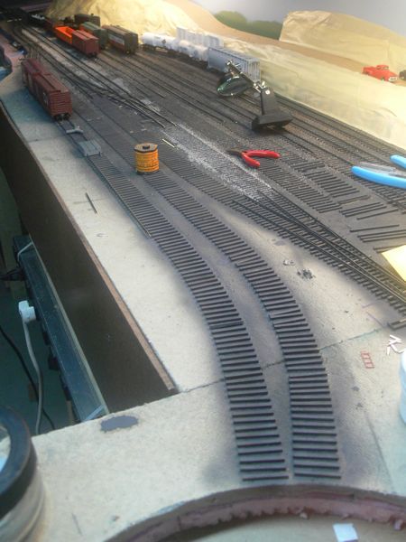
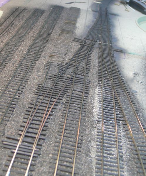
First up was connecting a code 83 No. 6 crossover, and a code 83 No. 6 left hand turnout. Ties are glued to the homasote.
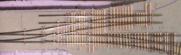
The cross over anchors one end of the yard. The main line is on the bottom, the top leads to the arrival track and yard (both to be code 70) to the right, and the switching lead to the left.
The wood ties were left purposely long at this stage.
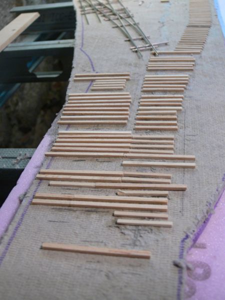
and with the switches removed for clarity
I marked out lines on the ties with pencil, and than trimmed them with a sharp blade.
With these in place, I can finish placing the ties in this section.
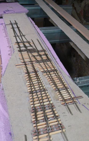
I assembled another couple of turnouts, and ran the ties along the mian that join them. As I have the quicksticks, I'll use them on the next couple of turnouts and just leave two aside for measuring and patterns.
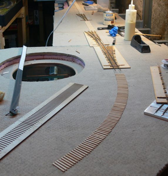
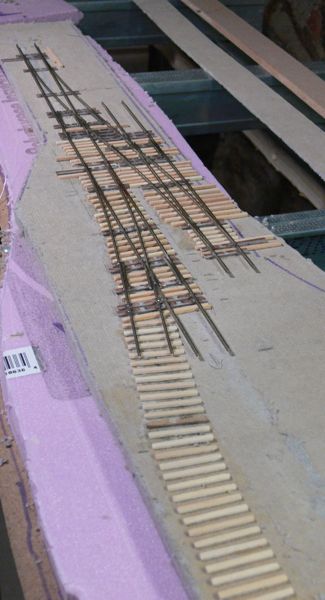
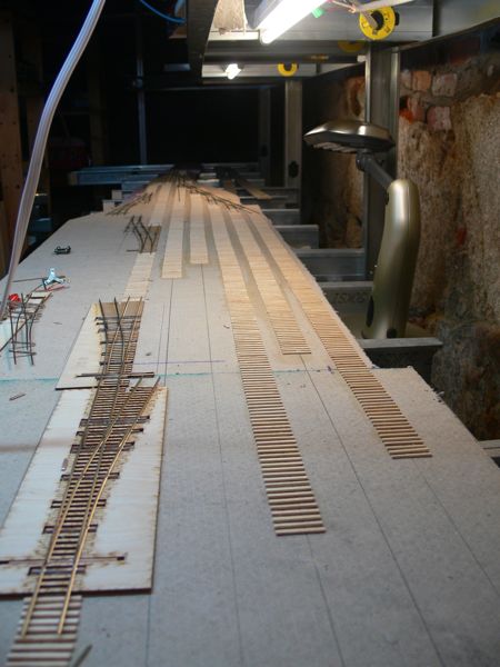
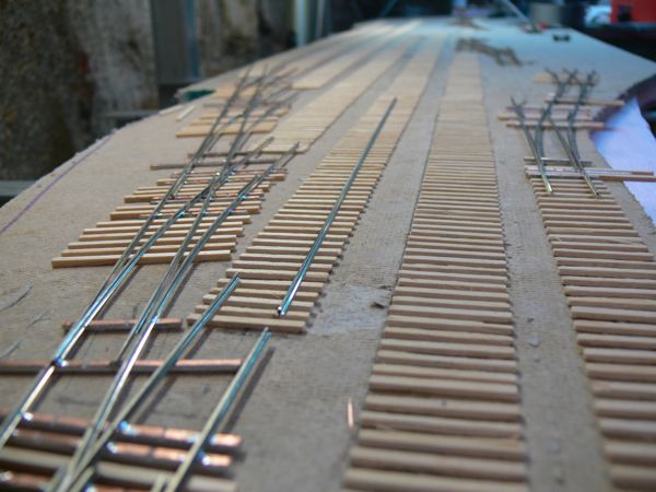
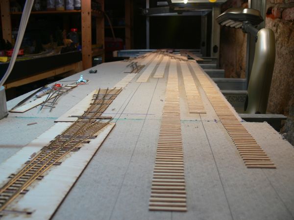
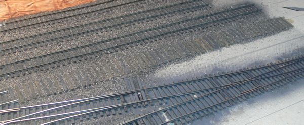
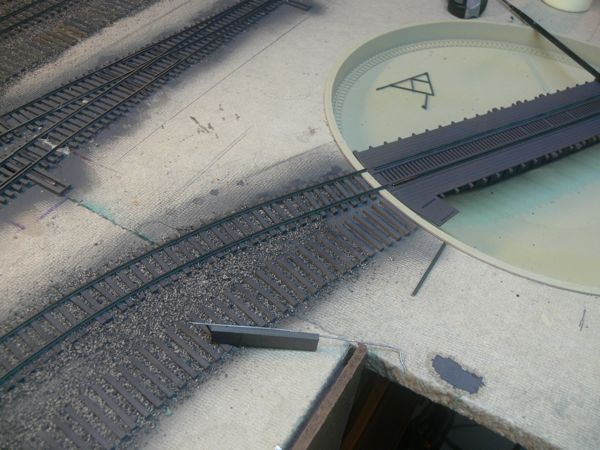
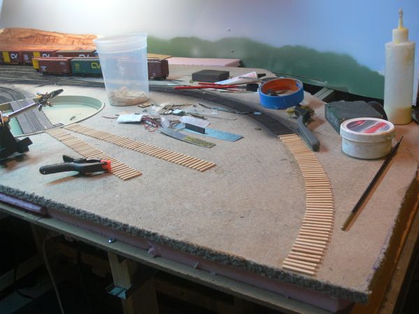
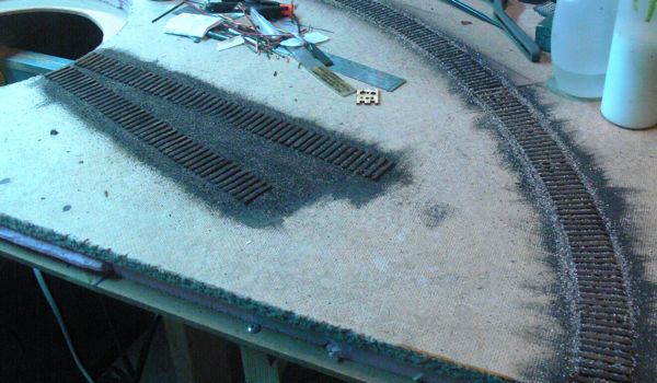
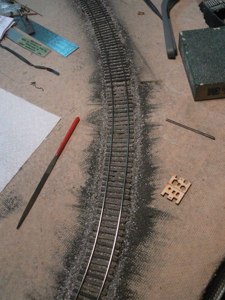
All of the No. 6 code 83's are done, and spaced out. I've begun drilling holes, and continuing to lay more ties along the main line - here is the first curve, behind the turntable pit.
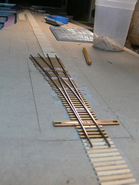
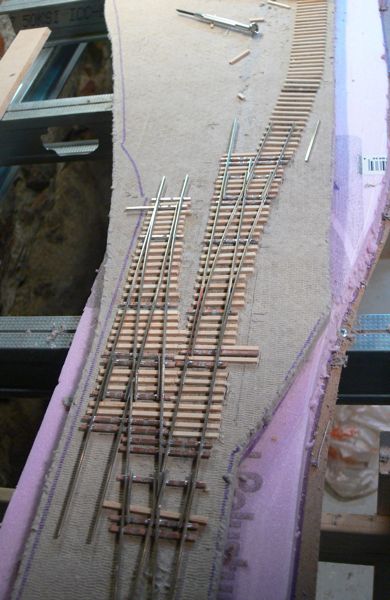
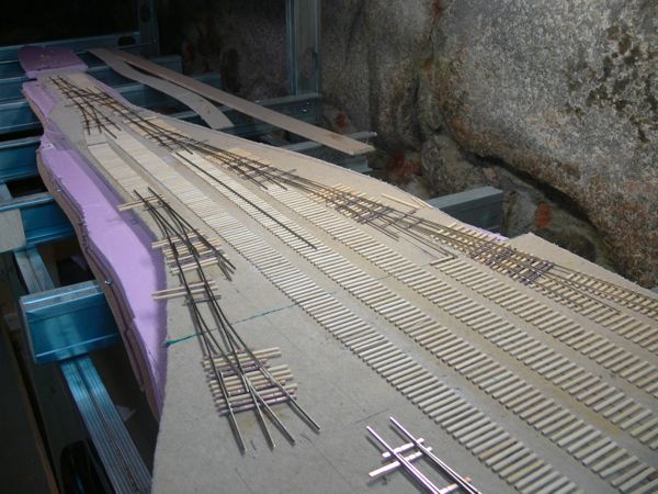
These are the quick sticks under the turnout - I chose to modify the Fast Tracks process, as the turnout is not glued to them at this time, but the ties are glued to the roadbed. This became quite tricky to do, but worked out as long as I was careful with the application of glue. You can also see in this shot that the mainline is complete all the way down. (well the ties are down at least.
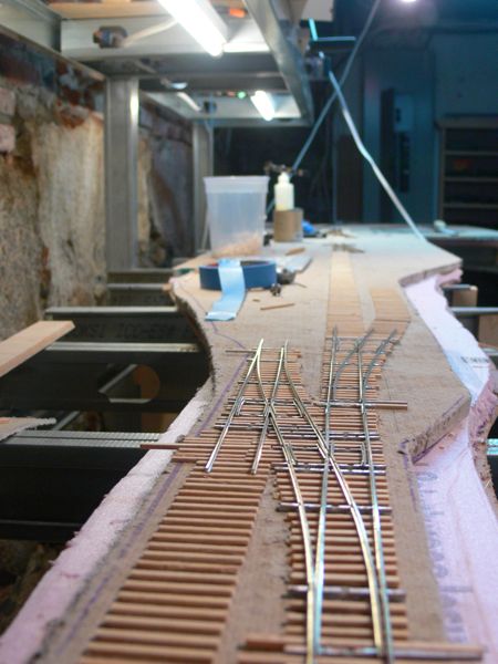
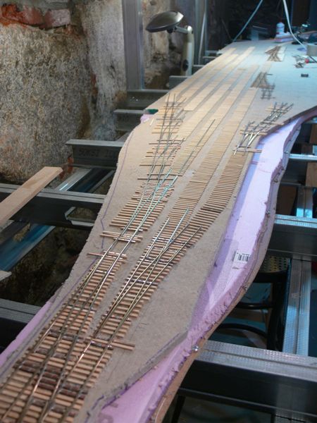
And a view from the other end.
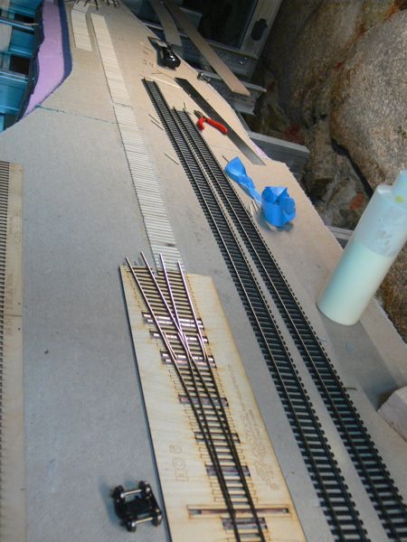
After a long delay, I finally received the code 70 rail I needed for the yard turnouts
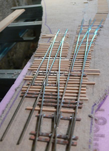
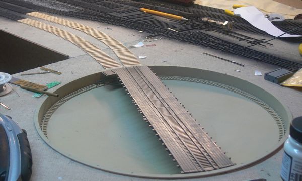
Thanks again to the Fast Tracks template, I went crazy, and made the ladder as a one piece unit. .
Yup, 4 turnouts in one!
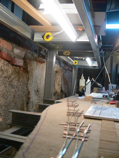
Hazards of working in the basement.
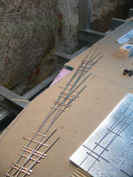
After about 5 hours, the ladder was complete
And passed electrical and running tests!
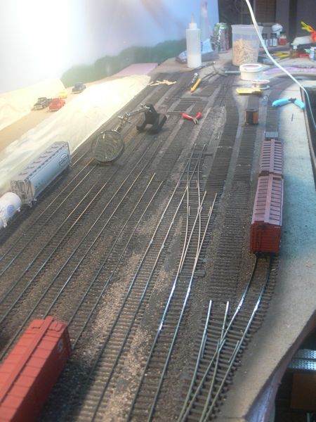
With the ladder in place, here oome the ties! Once I was certain on the ladder design, I felt comfortable enough running ties.
Besides ties, I also go another 3 turnouts put together, including the two in the lower left corner of this picture.
Looking back from the yard entrance. You can see another completed cross over to the upper right. After this, just one more cross over, and the yard turnouts are done.
Close up view of the ties that are in place.
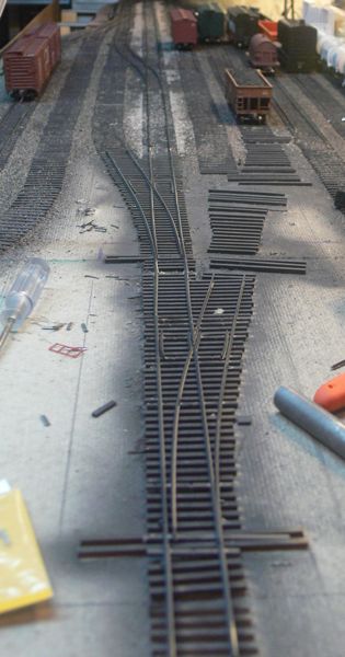
This is the last of the turnouts - not a true cross over, but instead the diverging rails of the right hand No. 5 lead into the main route of the left hander.
These feed from the mainline code 83 No. 6
The other turnouts got their ties
and the yard ladder has all ties down, and is ready to run electrical.

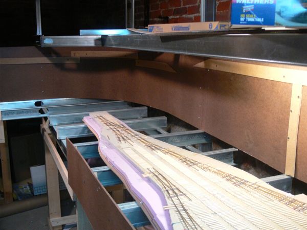
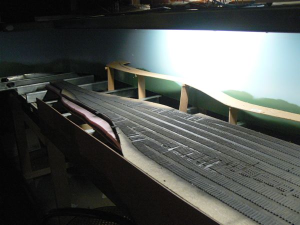
I picked up a piece of 1/4 inch hardboard for the background and fascia. Here is the background in place along the lower lever. The "cleats" you see are where I intend on attaching the cardboard strips. I'll paint above those.
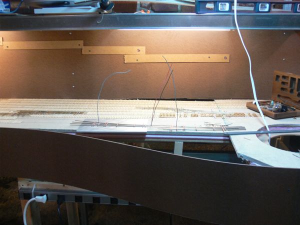
For the moment I've bent and curved the front fascia, however I realized that this might be a good place for my Easy DCC head unit, so I'm going to go back and square off the area instead.
I've also started wiring the switches. First up was a feeder to each frog, and in this case, I soldered on rail connectors, and than feeder wires to these in turn.
Back to the background, I fired up the airbrush for the first time, and hit the areas above the "ridge" lines.
With a healthy bit of it done, and me out of paint, I went ahead and started with some cardboard strips.
Hot glue and a weave. One thing I realized is that I didn't leave as much room as I would have liked along the far track.
I resolved that in the next section by adding the large flat piece of cardboard first, and than the vertical strips. Here is the section covered in masking tape.
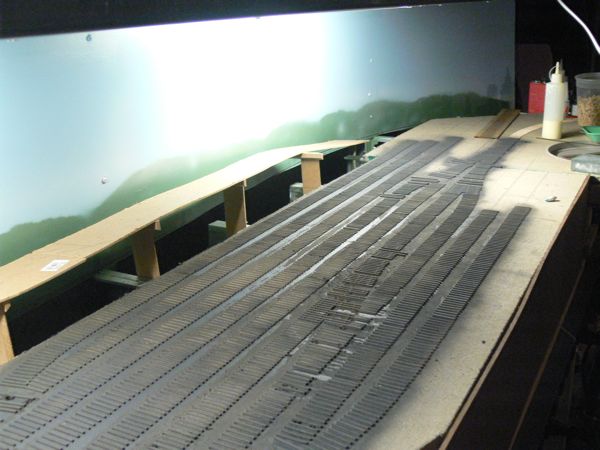
After some discussion on line, I ripped it all out. It was simply too steep, and too close to the edge of the track. With the cleats gone, I filled the screw holes, and primed the backdrop with PVA primer.
Once that was dry, I rolled a coat of Sky Blue from Behr.
The camera is not picking up the color for some reason, so here's a photoshop adjusted image.
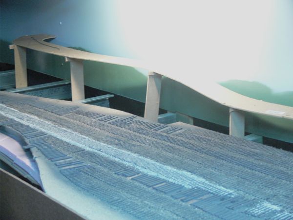
It needed another coat of blue, but before I did that, I tried a can of Sage green from Krylon and made a quick cardboard stencil for these hills. They reside well below the current scenery level. The risers you see are for the road along the back.
The road is made of MDF, and spliced in the middle section.
A series of fancy pants clamps hold the road to the risers for gluing.
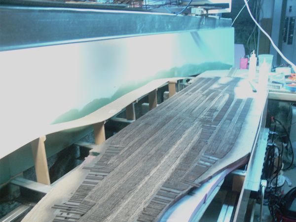
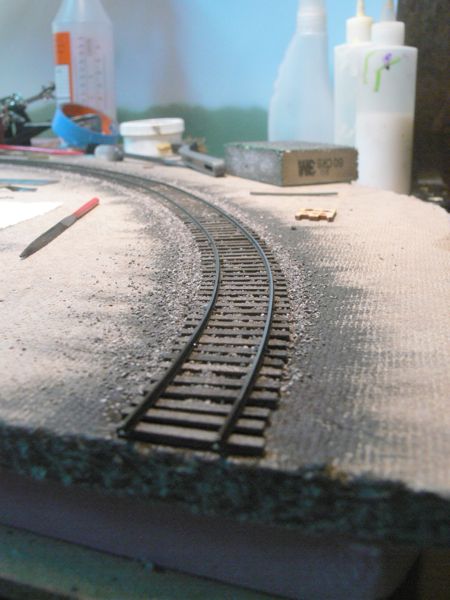
Next up was paint. All of the ties in place got a nice coat of weathered black.
and than ballast. Cinders for the sidings, my gravel mix for the mainline.
The first turnouts go in, complete with a blue point underneath each! I hand laid the bit of track you see coming off the top, and it checks out in perfect gauge.
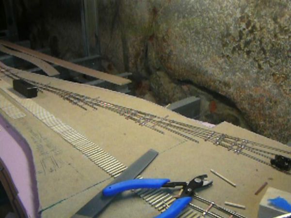
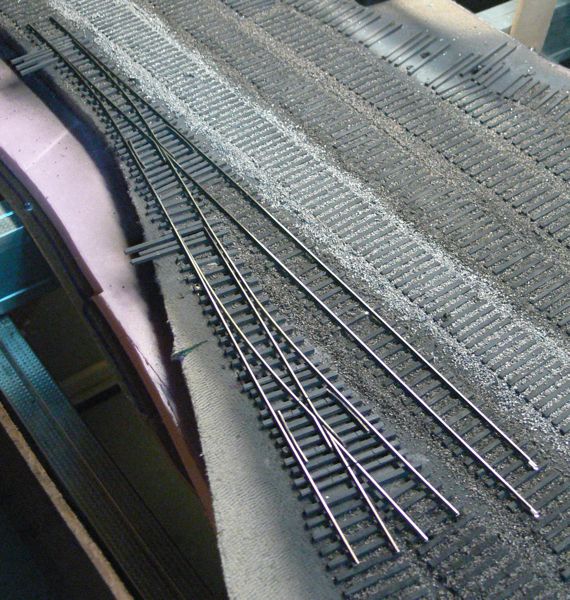
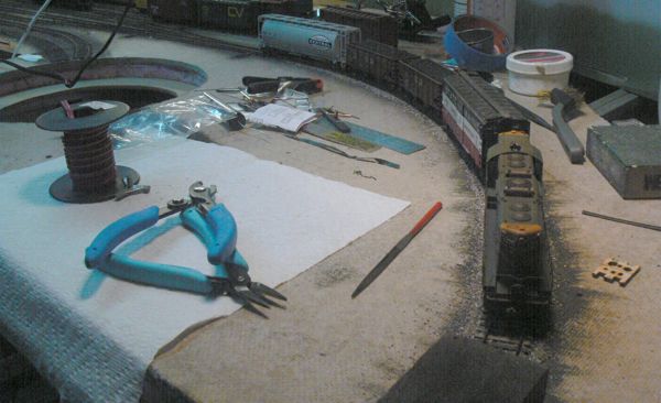
Track laying has begun in earnest, and here are the basic tools I'm using. I've found it better for me to spike both rails at the same time, I use the spacer block on the right to keep the rails in rough alignment on the ties, and the actual Micro Engineering gauge on the left to keep them in alignment while I spike.
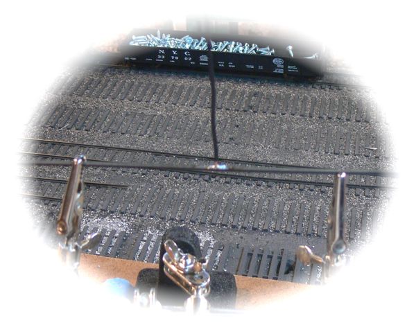
For power feeds, I've been soldering wire to the bottom of the rail. Here's a piece of rail upside down, after cleaning off the weathering to bare metal, the feeder is soldered into a vertical position.
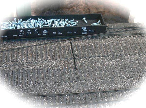
and than fed down the pre-drilled holes.
Once in place, it will be invisible with a touch of ballast.
and spiked in place. The heat from the soldering iron does alter the weathering on the rail, but I'll be going over everything with touch up paint later.
The yard so far. Yup, that's a locomotive, I have the feeders hooked up to the bus, and am running DC trains!
Playing with the turntable, I ran the two leads into it from the engine servicing tracks
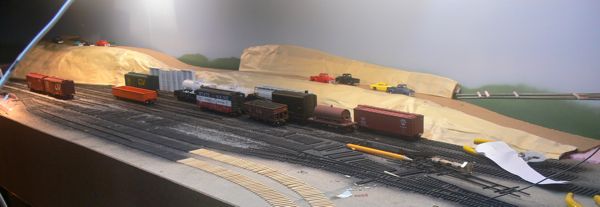
And back to scenery - cardboard strips hot glued in, covered with just tape at this stage. The nice thing about this is now there is less danger of my rolling stock taking a dive.
A closer view of the road and back ground hill.
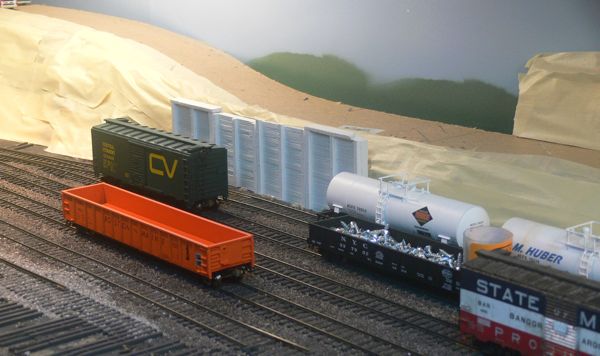
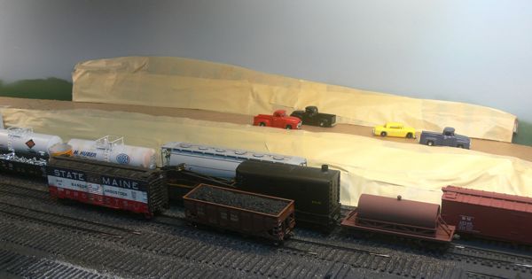
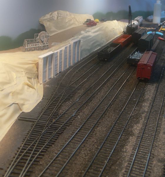
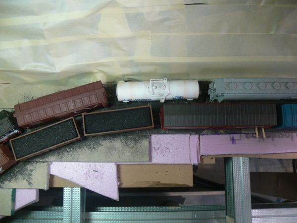
I was still too close to the yard for my liking, so I cut away the tape and cardboard and inserted these sections of plaster retaining wall I had left over from the previous test layout. They are cut in half, and than in turn hot glued to a length of MDF, and the whole thing hot glued in place to the cardboard and tape. They look a bit high now, but I think some scenery will resolve that issue. I might even put a parking area on top!
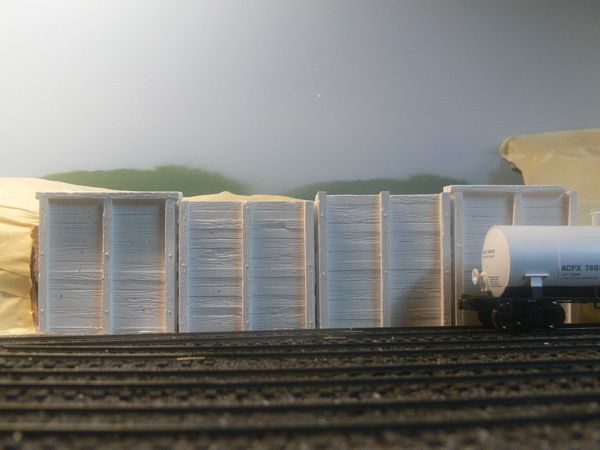
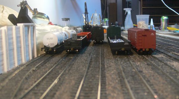
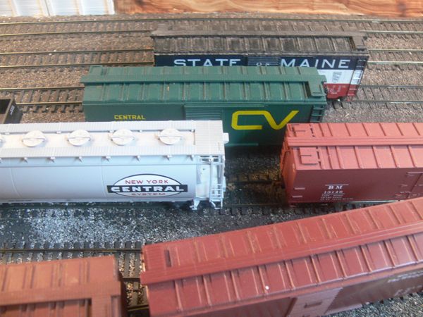
Here's a close up of the retaining wall, with a car for scale.
I painted and installed this cross over as well.
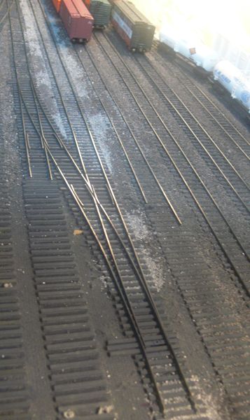
In this shot you can see the small pieces of rail that I had to use to connect to the cross over, next time I'm going to try and be more aware of spacing when I put down full piece rail lengths. It would have been wiser and more attractive to have had the connecting pieces a lot longer (but notice you can't tell in the picture above, here, the unpainted rail joiners reflect the light.
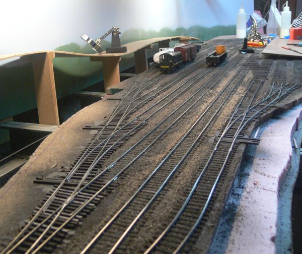
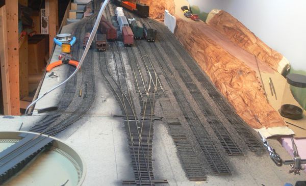
Gratuitous Fast Tracks yard shot. I realized that I made another big mistake - the yard is not code 55, but 70! I mistakenly used my 70 rail, I was kind of wondering why the transitions were so smooth! I only found this out this evening, when I found my complete, sealed, package of 33 3' lengths of weathered code 55! Naturally, now I'm out of 70, and I'll have to order another dozen pieces to finish this job.
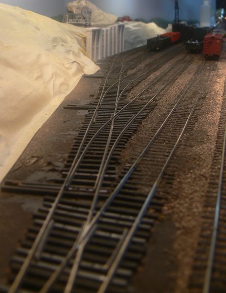
The yard ladder
With the airbrush out, I painted the turntable leads, but I'll need some rail (code 70) before I can finish them.
The weekend saw this pair of turnouts in place, as well as ballasting other areas. I know I did more, but there's not a lot to show, unfortunately.
and another quick look looking down the yard
The last pair of switches go in, and the ties are down for the RIP track
With the rip track ballasted, I'll be able to lay rail and finish it.
I tried rail tie brown mixed in with the weathered black, and hand painted these instead of the airbrush.
I also laid one of the turn table leads
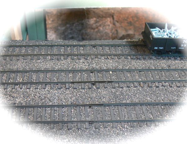
Here's a shot of the 12 scale foot track spacing. It's too tight, it makes reading reporting marks from an operator's viewpoint very challenging.
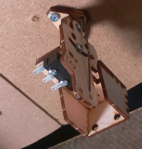
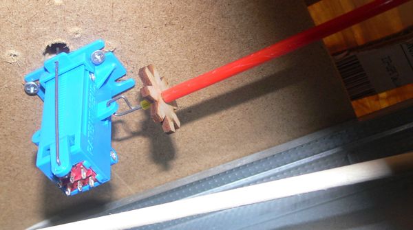
At the Hartford NMRA show, TIm Warris of Fast Tracks announced their new Bullfrog turnout controller. I picked up two, assembled one, and installed it.
I'm actually able to control these with nothing more than a piece of dowel, a screw, and a knob.
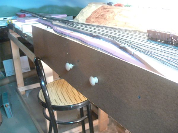
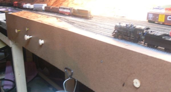
With the first in place, I added a second. Here's a shot of the Fascia
and from above - this second one is actually at a pretty good angle.
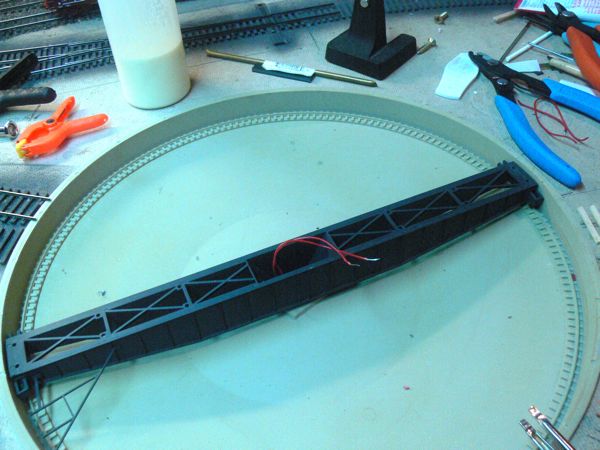
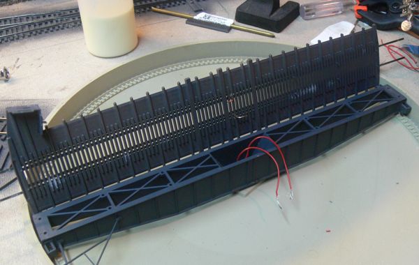
I had already painted the bridge, and the pit (aged concrete), so I figured it was time to get busy with the rest of it. I assembled the electrical connections on the shaft, and was impressed with the brass collar way of getting power up. However I broke one solder point under the rail due to too much wire in the cavity (this was following the instructions to use 5" pieces), so I broke all the rail off, and trimmed the wire a bit shorter.
I really wanted a rock solid electrical connection on the bridge, as this won't be easily pulled apart. I was unhappy with soldering the wire to the bottom of the rail. I found the contact area too small, and if the wire was bent in a 90 degree angle, it sat too high on the ties. I considered removing more of the plastic ties, but finally decided that instead of a soldering the wire to the bottom of the rail, I'd attach it to the outside. In order to provide clearance, I used the Fast Tracks stockaid to file off a bit of the outside edge of each rail. I didn't need to use the stockaid, but as I had it handy, well, it was!
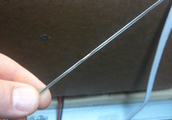
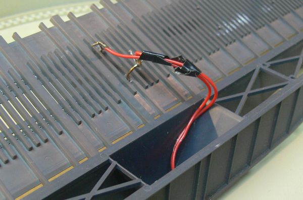
next up was stripping a solid piece of 16 gauge wire to a two inch length, and bending it so it came up underneath and wrapped around to the outside of the rail. This was than soldered in place.
You can see from this view that the wire isn't that ugly, and I think gives a very solid connection.
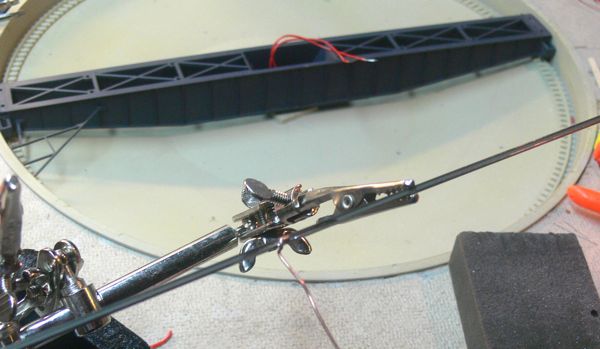
With those soldered, and the rails glued in place (clamped for an hour or so), I than flipped it over, and bent each feeder 90 degrees in opposite directions. This allowed me to loop the wire in the bridge around the bend, and solder it home tiight for a nice solid electrical connection.
with the lack of excess wire in the well, the top fit right on easily, and was glued on. So how did it work? Not well, I had no electrical connection from the top to the bottom. With the multimeter, I was able to confirm that the contact from the brass rings on the shaft to the rails was perfect - it was the damn wipers. Getting those to contact the rings, and only the right ring became a real pain in the butt. I finally cut away an inch wide "window" in the bottom of the undertable motor compartment so once it was in place I could line them up with a screwdriver. And than it worked - but only if you spin the thing in the counter clockwise direction. Spinning it clockwise somehow throws off the wipers. I suspect that the shaft isn't spinning perfectly evenly, hence it will throw off the wiper in the wrong direction. This is somewhat confirmed as the table grinds a bit when you move it. So after all that, well, it works. See for yourself. With that kind of working, I finally went back and laid the curved mainline and drill track on the far left hand side of the layout.
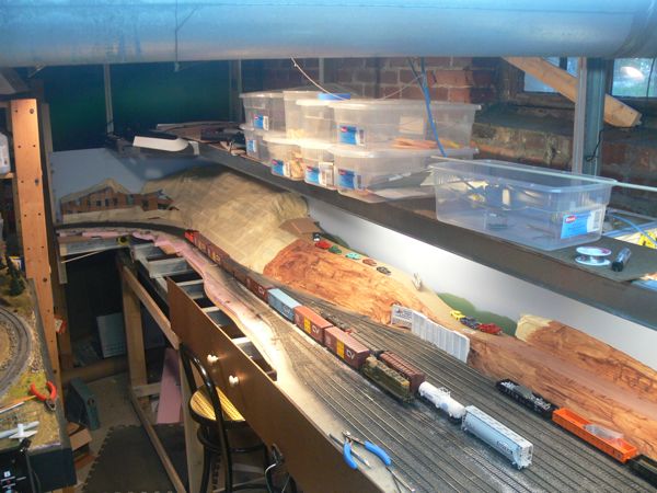
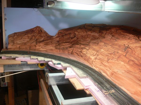
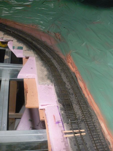
The curves in place - along with a lot of the corner terrain base.
I stained these ties in place instead of painting. I think they look a bit better than the painted ones.
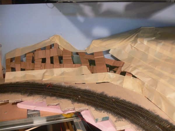
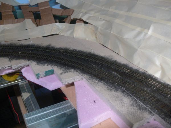
they're a bit more brown as you can see in this picture. Cardboard and masking tape makes a great sub-structure for terrain. Note that I ran out of masking tape.
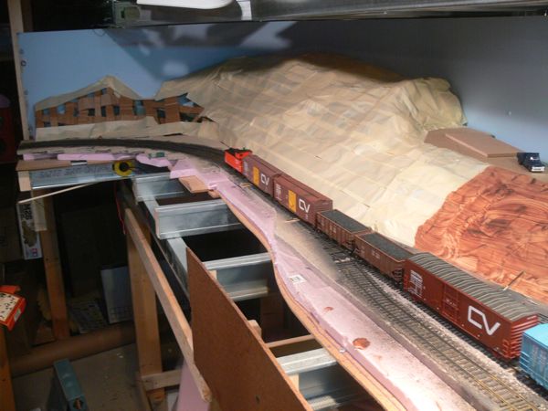
I haven't ballasted these yet, as I needed these tracks as soon as possbile to operate - I'll come back and get them.
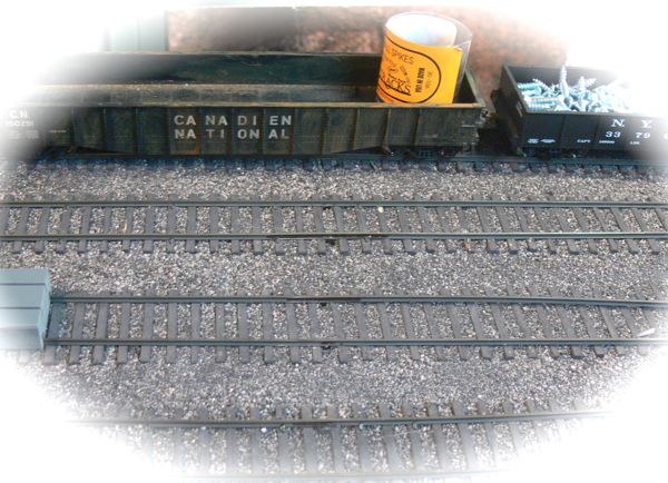
Clearances are, well, a bit too tight as you can see. It works, but consider this a lesson learned.
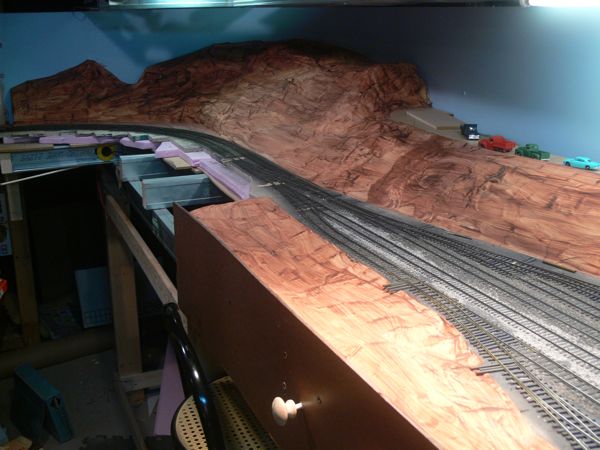
Armed with more tape and some brown cheap paint, voila!
The last of the ties for this test layout went down.
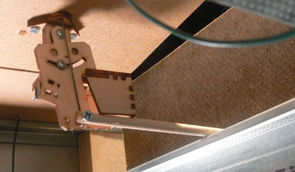
And I installed a couple more Bullfrogs with the Fast Tracks control rods.
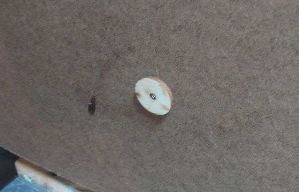
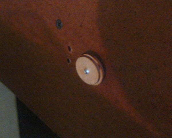
Here's a close up of the pull for the control rod
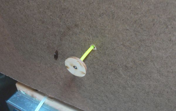
and at full extension.
The first one I assembled wasn't that pretty, but it works!
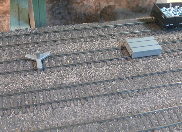
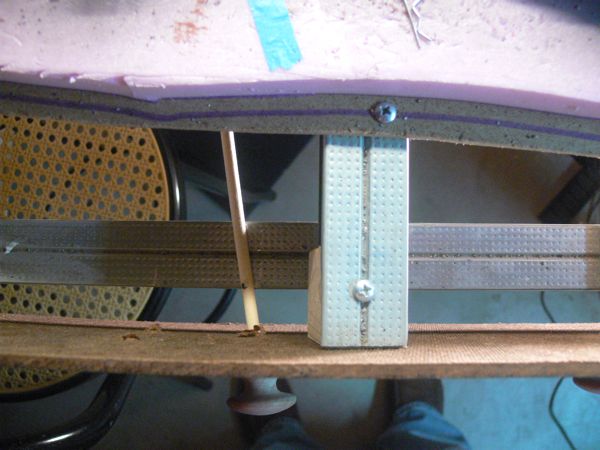
I had enough left over from the regular installation, that I used it to on this bluepoint that was close to the fascia. Note the wire adapter is nothing more than left over throw wire bent around, both ends inserted into the control rod with glue. The star shaped thing is the "wrench" to help you twist on the pull, I used it here to force down the wire, and left it in place as a sort of clamp.
The last few open ties were stained and ballasted
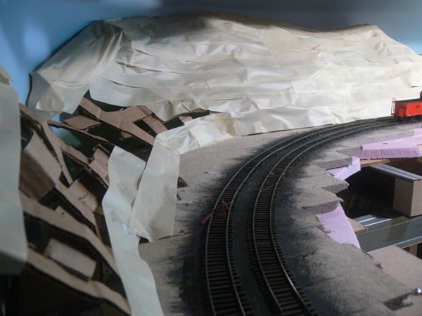
I tried spray painting the tape with a flat sage green, but I think it actually looks worse than the brown paint. It doesn't matter much here as it will get covered with plaster, but there you go.
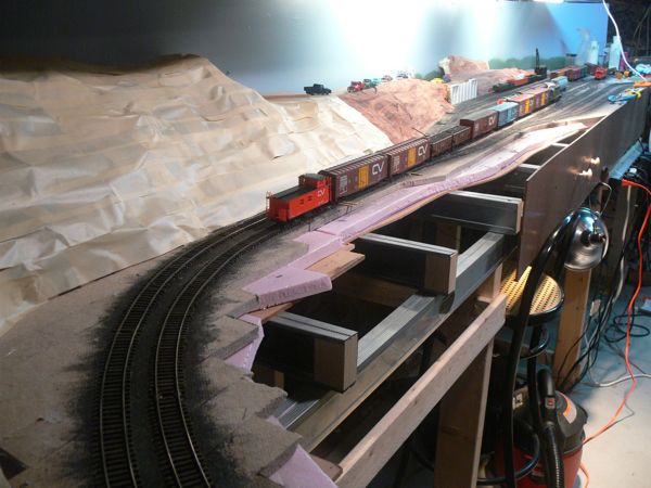
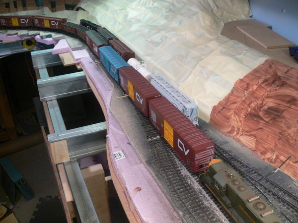
The first train runs along the new track work on the right hand side.
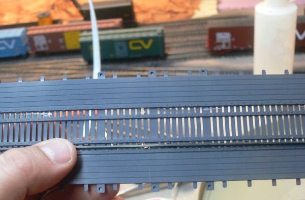
You can see the difference between the ties on the lower half (stained) and the upper half (painted) in this shot.
The end of the line! Other than two turntable leads, which await some turntable modifications the track work here is done. On to scenery!