Benchwork
As I approach the next construction, I am interested in using materials that would limit as much as possible material travel due to changes in humidity. At my domicile stabilizing the humidity level is simply not fiscally feasible, so I am wondering if there is another way to deal with the issue.
I would seem that changes to track work that are forced through expansion and contraction of the substructure can be negated if the substructure itself doesn't expand or contract. In order to do that, it must therefore not absorb or shed water. After some consideration, I've developed some concepts based on the following requirements.
1. Must be able to support a multi-level layout.
2. Must be strong
3. Must be allow minimal, if any humidity absorption.
4. Must be cost effective
5. Must be durable
6. Must be "mountable"
7. Entire units need to be free standing capable (I don't want it to be put against a wall.
Framework Substructure - Engineered Metal Studs
Engineered Metal Studs come in a variety of sizes ( Widths: 1-5/8 In., 2-1/2 In. and 3-5/8 In. Manufactured in 8 Ft., 10 Ft. lengths), and cost approximately a little more than twice that of wood (Approx. $4.75 per piece).
| Pros | Cons |
| Strong | Price |
| Durable | Conductivity |
| Re-usable | |
| Dimensionally stable | |
| Light |
Metal stud based construction is assembled with basic tools and screwed together in a similar method as traditional wood (a different saw blade is required). Knockouts are already in place for wire conduits. Appearance can be improved with paint or other treatments. Conductivity can be negated through proper wiring insulation practices. Price may be offset by other advantages, and may not be as relevant in the overall scheme of the construction (e.g. framework substructure costs with metal equals 8% of total layout construction cost as opposed to 4% wood materials)
Substructures assembled into standing units of three ribs on a 24" interval. completing a unit of 4 feet in total over all length.. Each rib consists of a single vertical piece in the back, four horizontal pieces to support from top to bottom valance, layout level, layout level, and storage. Each Rib to be connected to the others in its unit with longitudinal cross pieces that support the horizontal pieces.
Every other longitudinal cross piece can be staggered to join with other units when in place. Additional longitudinal cross pieces of other materials (such as wood) may be attached to the front of each horizontal piece to support fascia and other non-vital systems.
After running the numbers on the cost of an all metal structure, I went back to the drawing board. Re-evaluating the use of wood, I took a hard look at it's biggest drawback for my purposes, the contraction and expansion. I remembered, however, that the movement only occurs in two axis - the length of a piece of wood doesn't change, only it's width.
With that in mind, I wondered if it would be possible to use a metal support structure that can "ride" on a wooden subset. Interestingly, my first attempt at planning it kinda resembles rails on ties. By mounting metal studs on the tops of wooden posts, there is no vertical movement; and by making the drilled hole in the metal 1/8" larger than the lag bolt used to mount it and by only hand tightening, the metal L girder assembly (girder and risers) should be able to float back and forth if needed, keeping the railroad above it in a stable situation relative to itself.
I cannot think of a way currently to support the upper level and valance without using a metal stud; my thought here on assembly is to fix the vertical stud tight to the L girder assembly, but again using the same method outlined above, only "loosely" attaching it into the lower part of the wooden legs (mostly to keep it in alignment.) Naturally the risers of the L girder assembly can be extended out well past the basic unit dimensions.
These are designed as 2x4 foot units that would be connected by pieces not shown. For the top, I think connecting multiple pieces would provide the lateral stability needed, but additional bracing might be required.
Schematic Drawings
Front view of the proposed hybrid benchwork
End view of the proposed hybrid benchwork
With those plans in hand, I began construction of one side of the next layout.
The basic leg unit. I ended up using 2x4 stud lumber for the leg posts (cut to 37" long) as our Home Depot didn't have 2x2s. As it turns out, there is another advantage here as well.
Once completed, each leg sub-assembly should be able to stand on it's own (that means it's nice and square). If it doesn't, fix it now.
I use these clamping squares from Rockler to make sure every thing is nice and square before screwing it together.
With the back cross pieces in place. Flip, and do the front.
An assembled leg unit. It is 48" wide, by 24" deep, by 37" high.
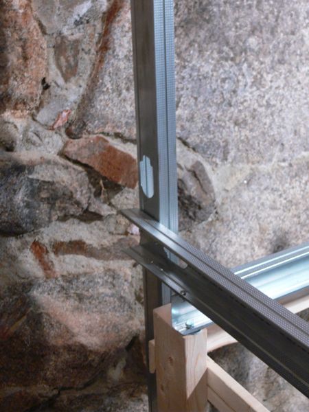
I cut the steel 2.5" studs on an older miter saw equipped with a cut off blade.This is the basic concept (not attached at this stage).
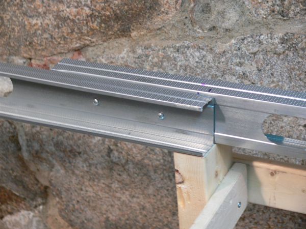
Close up of the mounting point. Washer between stud and wood, lag screw goes in hand tight.
And with a sheet of MDF on top I'm planning on using this laminated to 1 inch pink foam for the bottom of the roadbed.
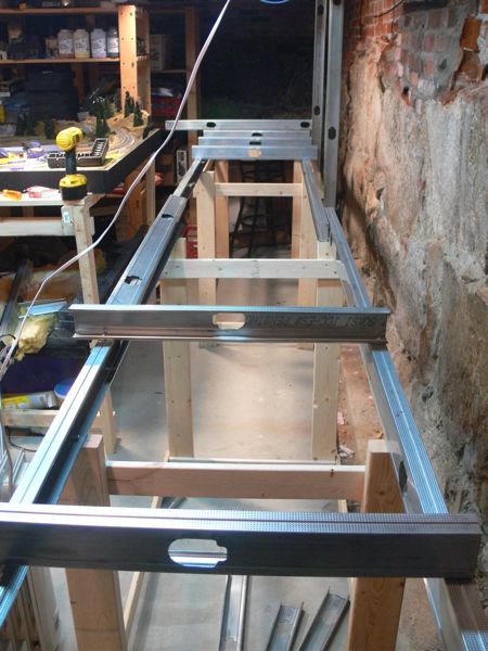
After assembling the other leg unit, I attached them together with the steel studs as joists. Here's where the 2x4 legs came in handy, my original idea was to slide one stud joist over the other (as they do nicely when inverted), however I was unsure on the slight difference in thickness this would provide. With the 2x4, there is plenty of overlap to put them side by side.
Here's one of the overlap areas - both joists are lag bolted into the leg, and than screwed together.
On the back, I started adding vertical studs. Note the stud is lag bolted twice into the cross pieces of wood along the back, and than screwed to the riser that extends along the back. The top structure was a bit bouncy, before adding this, now with it screwed to the vertical stud, it is very stable.
All four vertical supports are in place, and the starter for the second level attached.
All of the risers are also in place per the track plan.
I added these "screw blocks" cut from a 2x4 to each riser, to give the fascia a purchase.
1/4 inch MDF will be the first layer of the roadbed
followed by 1 inch pink foam.
A trip to home depot led me to picking up three of these rails - normally meant for the bottom and top of a stud wall created with the metal studs, this worked like a charm to make the grid support for the top level.
And lights. I picked up three of these 2 foot florescent. I modified them right out of the box by drilling holes in both ends
And than mounted it to a cross piece of the top level.
In place, and secured to another cross piece. Note that this is not secured to the rails yet, but can slide as I may want to adjust light coverage.
The were wired lights, so I had to run electrical. I used a framing outlet box and an outlet to connect the cut extension cable I used to tie into the Romex.
And how do they work? Voila! Only two are installed so far.
Costs so far - $109.71
| Qty | Item Description | Unit Price | Total |
| 15 | 2.5 inch metal stud | $3.70 | $55.50 |
| 3 | 2.5 inch metal track or rail | $4.90 | $14.70 |
| 4 | 2x4 inch wood stud | $1.97 | $7.88 |
| 7 | 1x3 inch wood strapping | $1.19 | $8.33 |
| 3 | 24 inch florescent light | $15.95 | $47.85 |
| 1 | package 1.5 inch #8 wood screws | $5.99 | $5.99 |
| 2 | package .5 inch sheet metal screws | $2.99 | $5.98 |
| 18 | lag bolt (1/4 inch, 1 inch long) | $.18 | $3.24 |
| 18 | fender washer | $.18 | $3.24 |
Note the screw packages should be enough to complete the project as a whole, and at this stage, at least another 5 steel studs are required for the remaining risers and second level.