 Da
Reapawagon (Battlewagon)
Da
Reapawagon (Battlewagon) Da
Reapawagon (Battlewagon)
Da
Reapawagon (Battlewagon)- 30 December 2008 - Gooba out of retirement? Hold on to your squigaritas, but not quite - but I did open my big gob, and offered to make a model if someone sent me the 2008 Ork Codex (as I am not supporting GW financially). Well, someone did, Blakkreaper from the Waaagh, and of course he asked for a battlewagon. Not just a battlewagon, mind you, but an example of the kind of battlewagon that I thought should have gone in that poor codex. Oh, and he wants a defrolla as well. I have decided to not include one piece of GW produced parts on it, at least through my part of the build (I'm thinking of fixing the weapon points, but sending off to him for it's weapon load out.)
So, easy enough. As I'm sending it to him when I'm done, I've decided to title this on da Reapawagon. This one's for all the old school converters out there.
If you have time, check out the rest of the site too - including the ork army list, and the other conversions.
so 'ere we go! Be Warned though, this is a long page with a lot of images, so your load time may vary.
 |
Ah, a clean sheet of blank plasticard. |
 |
I layed out the overall dimensions by eye, and split the card into 3 parts. I drew up a quick profile on one of the interior hull pieces, and satisfied with the direction it was going, I cut it out. |
 |
And than made a matching piece to go on the other side. |
 |
Internal braces, sketched out on a piece of plasticard. |
 |
And cut out |
 |
Braces being applied to the bottom piece without measure. Note the small scrap plasticard allows you to make it flush evenly while the glue dries. |
 |
One side completed. |
 |
And both sides ready |
 |
One side is glued to the base. |
 |
I had a lot of glue problems (an older bottle of Citadel Super glue - don't roll you're eyes, I'm not joking), so I added a few smaller vertical braces to support the sides. |
 |
And both sides glued in and drying. |
 |
I cut out the front firewall, and the back. |
 |
The front in place. Note the vertical supports |
 |
I added extra triangles on the bottom for the rear firewall |
 |
And some floor spans as well in the middle. Note the there is one attached to the rear firewall as well. |
 |
I cut out the floor piece for the transport section |
 |
And the whole shebang together. |
 |
The front plate mounted |
 |
And the front gun deck prepared. Note the extra glue supports. |
 |
No point in re-inventing the wheel, so attacked an old model I still had laying around. The M3 Sherman bogies didn't' want to come off of the hull easily, so instead of fighting it, I simply scored and snapped the hull parts away from the bogie area. |
 |
The insides ended up uneven, a few minutes with the Dremel took care of that . |
 |
Note I ran the dremel over the entire part, to roughen it up for gluing. |
 |
One side attached. Note I put the toothed wheel in the rear, as I didn't build any front mechanism on this model for a forward mounted transmission. |
 |
And with both bogie sets in place. |
 |
The gun platform base in place. |
 |
The visible part of the drive shaft is mounted |
 |
and the first vertical wall of the engine compartment |
 |
I added a crew door above the drive shaft. What, grots wouldn't walk across a spinning shaft as big as they are? |
 |
And the second vertical wall. |
 |
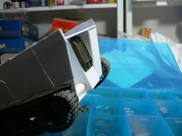
The flat back riser in place |
 |
and the slanted one. No reason to do it this way other than visual interest. |
 |
With a piece of gubbinz. |
 |
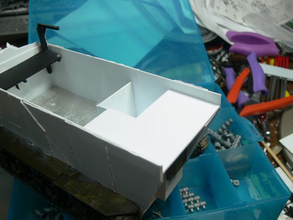
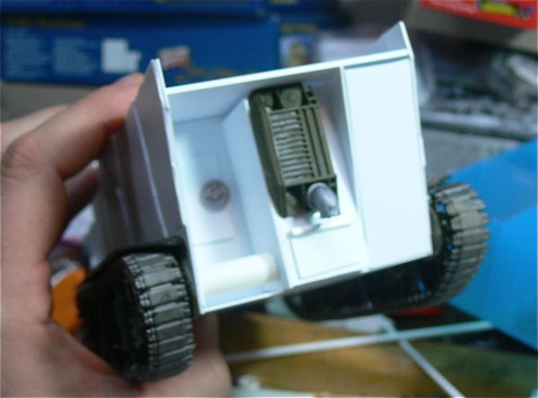
The passenger compartment flooring is down, as well as an interior wall |
 |
The interior engine room is complete |
 |
On the front, a piece reinforcing the bow goes on |
 |
and another piece or two - including an i-beam along the front bottom edge. |
 |
And a driver's window |
 |
Vertical support risers were added to the front end of the wagon. |
 |
And than two rail shaped irons were added to the bottom of each jaw for structural support. |
 |
And on top, a cut down i-beam. |
 |
Time to armor up the sides. I started by cutting up random pieces, worrying the edges with a dull knife, and than attaching it to the inner hull. |
 |
The right side skin grows. Note the varying thickness of plastic |
 |
And the right side "skinned" |
 |
And the left side as well. |
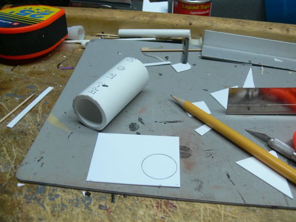 |
Construction on the defrolla. Based on a piece of 1 1/2 inch pc pipe. I placed the pipe end on the piece of plasticard and drew out the interior diameter. |
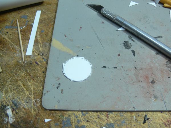 |
and a rough trim of the plasticard piece |
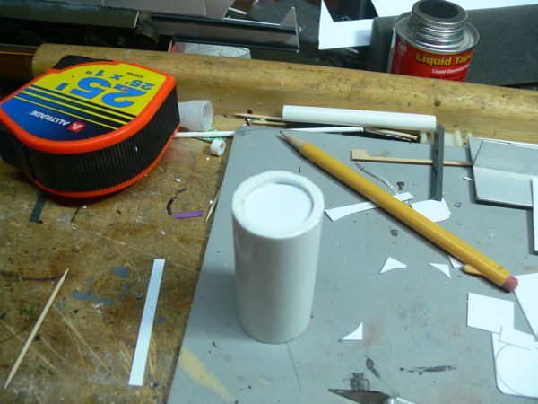 |
After shaving it down to just outside the pencil line, it slides into place, and gets glued. |
 |
and resting in place. Too Small? or should I do TWO defrollaz? |
 |
Next up was adding spikes, and sectioning off the defrolla. Before I go ahead with two, I wanted to see if it would bulk out at all with some details. You can see I used a couple of thin strips of plasticard to define areas on the roller, and the spikes are made from plastic rod, shaved down. |
 |
And with center ribs in place (also cut down plasticard strips) |
 |
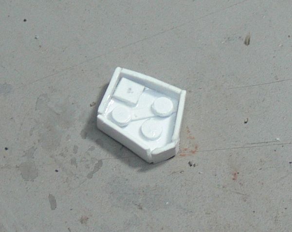
I found this old piece that I had snapped off of my basilisk conversion a few years back, oddly enough it fit perfect as a gun step. Better yet, and hard to see here, is that the floor plate is diamond pattern. |
 |
From the front, the gun step got an additional piece of armor plate (well, at least along part of it) . |
 |
And one more piece of armor up front, just because. |
 |
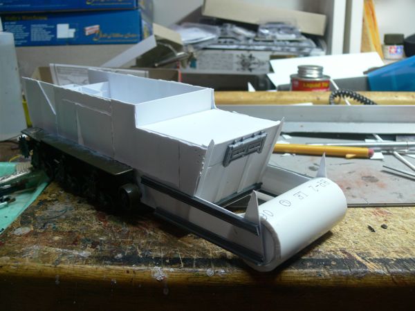
And with the defrolla in place. I'm still not totally sure what to do in that dead space, but the roller is a bit better looking at this stage. |
 |
So as you can see from this side shot, there is a bit of a gap that needs to be filled. My concept on this was to integrate the defrolla into the design from the start, but perhaps it might be better to tack it on afterwards as most folks do. In this case, however, I cannot simply cut the front down as it would ruin my design concept. |
 |
I toyed with the idea of sliding it further back on the front pieces. |
 |
and than with having a "grot" step or similar feature. |
 |
After playing with it a bit, I decided to go for the latter. First up was adding some tubing for the support structure. |
 |
Two pieces went in parallel. Note the small strip of plasticard under them, that holds them in vertical alignment. |
 |
With those in place, I added to angled supports from the bottom i-beam, and two more horizontal ones from the main hull. I was considering doing a plow type structure on the bottom edge to allow the machine to ride over any thing that remained from meeting the rolla, however I decided that would be more complicated than it was worth (as it will be mostly invisible). Instead, is a thickened skid plate that should allow for the same purpose. |
 |
And the "grot" deck in place. I figure the final owner can put what he likes here as far as other details or riggers. |
 |
With that in place, I completed the skid plate with another piece added to the top. |
 |
And with the defrolla positioned. |
 |
I think this works - and better yet, I think it will work nicely with the next step I have in mind for the front. |
 |
Rivets! Everything looks better with rivets. I did the front sides first in case my next steps covered them up. |
 |
And the other side riveted up |
 |
The first of the "teef" go down on the outside. by using a T shaped bottom beam, the teef sit in side of it. |
 |
Holding the back toof in place, I marked the clearance needed to get around the track. |
 |
and than cut out the marked area on the back toof for the track clearance. |
 |
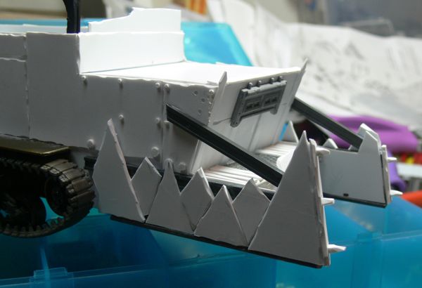
And with all of the teef in place. |
 |
front plates were put in place on the front teef. |
 |
A few spikes were added to the front plate |
 |
The right side with rolla |
 |
The other side, with the front broken "toof". |
 |
I think it's starting to shape up... |
 |
A couple of additional iBeams for some vertical "impact" support. |
 |
And another row of "teef" |
 |
I think the additional teef help with the sides. |
 |
The right side got the extra teef as well. |
 |
And moving to the back, I added a large plate covering two of the three mechanical rooms. |
 |
On the back, I removed the one bit I had there already, and instead installed this grill from a 1/35 scale 2 1/2 Ton truck in a vertical orientation. |
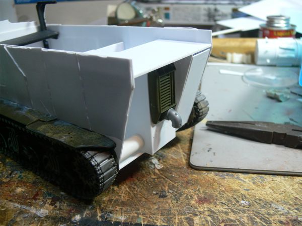 |
Best yet, the Chem plant kit pipes actually fit perfectly over the headlight. Basically snapped on! |
 |
I also added (kind of hard to see here, please excuse the poor picture) a wheel for the door, and another hatch below the drain . |
 |
More work on the back - a ventilated panel, and some more piping courtesy of the chem plant kit. |
 |
The louvers on the ventilated box are supposed to be different sizes, btw. |
 |
I had an inquiry off line about some of the tools I use (I think it was because of the calipers in the last picture). I started, years ago, dedicating 10% of my modeling budget towards tools themselves.One of the best things I've picked up (besides calipers, and bulk #11 blades) is the Duplicutter II from Northwest Short Line. This is a great tool for plasticard, and allows you to set the desired width, and than cut it out constantly. If you plan on doing any large amounts of plasticard work, this is well worth the $30 (approx.). |
 |
And two stripped pieces. Note the curve on the bottom one was NOT cut on the duplicutter. |
 |
These pieces have a purpose. The length was measured as one piece, than it was cut up randomly. |
 |
And of the random cut pieces, the edges were worn down with the knife. Note that this looks a bit extreme at this stage; most things such as paint and details need to be done "extreme" to stand out on the tabletop. |
 |
And the four panels in place. Yes, it was time to cover the old model parts. |
 |
Both sides get the treatment. Note the plates are staggered at different intervals. |
 |
Two more strips are cut, these a bit thinner. |
 |
And than divided up into thirds (again aproximates). |
 |
Once cut, I added the internal "hinge" to the them. Note they were spaced out just a tad while the glue dries. The T-shaped metal straight edge is also another invaluable tool in my shop; here it is being used to align the pieces as they dry. |
 |
And the two sections ready for mounting. |
 |
I inverted the rig, and attached the side panels. Note that I did this now, while I have a lot more work to do on it as a test. This is going to be mailed to Australia, and if these sides panels can't hold up to my constant handling over the next few weeks, than they won't stand up to shipment or continued game play. I want to break them if they do before I ship it.(if I do, I'll add bracing on the inside, angled from the inside of the bogie set. I also want to stress patience here. The side panels I allowed to dry for a half hour before mounting them; I waited for another half hour before taking pictures. I will be out of town for 2 nights; I have re-inverted the model, and by the time I return the glue will have had plenty time to cure. |
 |
The right side. |
 |
And the left, with the def rolla resting in place. Overall, I'm quite pleased, this is moving closer and closer towards the design I've had in my head for while. With these plates in place, I think the Teef really begin to pop. |
 |
I added another small segment of I-Beam across the top. |
 |
And than started to run an upper layer of Teef. |
 |
I didn't like the way it was looking, so I removed the front teef, and left the back ones. It was closing in the front too much for my taste. |
 |
Rivets! Here's how I do it. This isn't the best way, or the only way, but the way that I do my rivets. First up, the tools, cut rivets from my punch, a piece of extra plastic with super glue plopped on it, and a sharp exacto blade. A fresh tip is the important part. |
 |
Spear a rivet |
 |
and dip it in the glue |
 |
Apply it to the model, and roll the rivet off of the knife point by twisting the knife and applying pressure to the rivet. |
 |
|
 |
I riveted this entire side today. The other side has yet to be done - note that with big rivet jobs, I prefer to break it up into sections. |
 |
I was asked for measurements, so here you go. Length. |
 |
Width. |
 |
And height (so far). Yeah, its zoggin' big! |
 |
Worky Bitz! I know and love the boiler look, but not all machines in the 41st Century are steam driven. I'm hoping to get a more high tech look here with these parts. |
 |
Note the box (platform) being made down below for the chem plant part to sit on. The long tabs get cut off after the glue dries. |
 |
The platform is finished, and the chem plant piece got another half piece of pipe added to it's length to break up the look a bit. |
 |
And in place on the platform. |
 |
A test fitting of the top "turbine" unit. Don't let the color of this throw you off. |
 |
Test fitting the exhaust unit. It's made up of a cut down piece from the chem plant, as well as some plastic tubing. It's not finished either at this stage, so be patient! |
 |
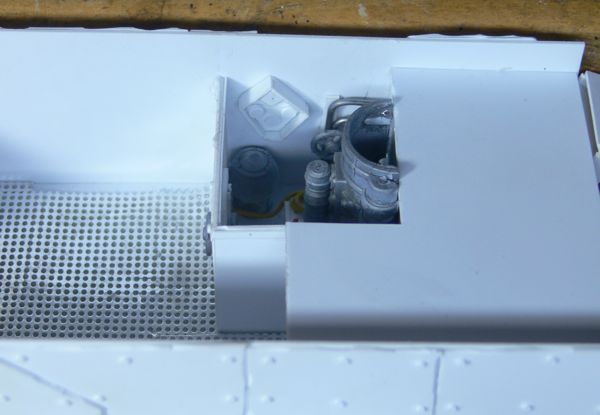
I decided to put some work on into the inside of the engine compartment. I made this pipe assembly with solder and a wheel from the chem plant. I attached it to plasticard first (the thin strip on the back) to make the final installation easier. |
 |
And than with the loose bitz, including the assembly in place. Note the two sided door and loose wires. |
 |
another view |
 |
and one last one |
 |
back to Mr. Fusion (I've since decided to not make this a stack, and instead make it a fusion reactor), step one was adding some orky plates to the sides. |
 |
I than cut down the pipe, and sanded it flat. This top piece is glued on, and will be trimmed to fit later |
 |
With the top temporarily in place. Now I'm not sure on the orange piece...note Mr. Fusion still needs to dry as he is before I can smooth down the top. |
 |
Once the glue dried, I was able to sand and file the top part smooth. |
 |
And than riveted up the side plates. |
 |
I added some ribbing on the inside walls, and started to apply rivieting to that as well. |
 |
Hello Flux capacitor! Painting will help this part I think. |
 |
And mounted on the side wall. |
 |
Back to work, and back to riveting. First up was the left hand side |
 |
Than the back |
 |
And finally the front. With this out of the way, it's time to move onto the weapons! |
 |
First step was cutting three identical plates (cake layers, I call them) measured against the over all dimension of the turret |
 |
and than I trimmed off 1.5 cm corners on the rear so it will swivel to a degree. |
 |
and trimmed off the other two plates to match |
 |
I than cut another 1 cm strip (well, a bunch actually, and began forming the first layer of the turret cake. |
 |
These internal ribs are not to be seen, but provide valuable support. I didn't cut any of these, they were all scrap, hence the hodge podge look. |
 |
and the first layer of the cake topped with another plate. |
 |
The second layer of cake went on, the one side enclosed (i cut down the last cake layer piece, both along the right edge, and he front by .5 cm). |
 |
And an outside gun shield to match the enclosed side. |
 |
a quick sub plate when on the front as well. You'll notice these are not super tight fitting - there's a reason. It's all just sub-structure, and will be skinned. |
 |
Skinned like this. Here's one side and the rear |
 |
And the other. |
 |
On the wagon |
 |
The size fits the model nicely I think |
 |
some rivets, and we're good to go |
 |
A demonstration of how the rear angles should help the clearance. |
'ere is dem nasty legal bits:
This website is completely
unofficial and is in no way endorsed by Games
Workshop Limited.
Dark Angels, Eldar, Games Workshop, Warhammer, Adepta Sororitas, Adeptus Astartes,
Cadian, Catachan, Citadel, the Citadel logo, Codex, Dark Eldar, 'Eavy Metal,
Falcon, Fire Prism, the Games Workshop logo, Games Workshop, Genestealer, Slottabase,
Immolator, Leman Russ, Mordian, Necron, Ork, Predator, Raider, Ravager, Space
Marine, Tyranid, Ultramarines, and a bunch of other words, are trademarks of
Games Workshop Limited. Used without permission. No challenge to their status
is intended.
©2001-8. This site is the sole work of Scarpia (Thomas Garbelotti) unless otherwise noted. All content not created by Scarpia is copyrighted by the respective copyright holders.